Buck Converter
Please Log In for full access to the web site.
Note that this link will take you to an external site (https://shimmer.mit.edu) to authenticate, and then you will be redirected back to this page.
As mentioned in the pre-lab, this lab will explore a couple of different circuits designed with the same goal in mind. Our context for this lab will be powering the familiar Teensy microcontroller we've used before, but we'll try powering it from a source with a higher voltage. This is an incredibly common application, taking a high voltage (for example, the 120V power mains) and converting it down to a lower voltage needed to power a device (for example, 12V or 5V); and our goal is to do this conversion both accurately and efficiently. In practical applications we may be further limited by volume, mass, cost or reliability, making the design of each power converter an interesting and fun optimization!
For our purposes today, we'll be stepping down an 11V source to something smaller to power our Teensy. The Teensy doesn't require exactly 5V to work; in fact, it accepts quite a wide range of possible voltages. To start, let's target making approximately 8V from our 11V source.
1) Resistor Divider
We've already seen one way of doing this, with a resistor divider:

The "load" is the thing that we're providing power to with our converter. Later in the lab, the Teensy will take that spot. But for now, so that we can do some calculations, let's model the Teensy as a 120\Omega resistor. It's a really crude approximation, but actually kind of close in some ways.
Using this model, we can make a voltage close to 8V by choosing R_1 = 10\Omega and R_2 = 33\Omega.

Now let's do an experiment to see how this matches up against reality. Build this circuit (using the big chunky power resistors we have up front: the green ones are 10\Omega and the pink ones are 33\Omega) on your board, and using a regular 120\Omega resistor from the cabinet to represent the load, temporarily. Use the benchtop power supply (set to 11V, 1.2A) to power it it for a short while only, and while it's on, make note of the following:
- the voltage and current indicated on the power supply (these are the source voltage and current, which we can use to compute the power sourced by the supply),
- the voltage across the load resistor
Turn off the benchtop supply when you've written these things down. Be careful with the resistors, too, because they get very hot very quickly.
Don't tear this circuit apart; we'll need it for some more experiments later. But for now, disconnect the resistor divider from our input voltage so we aren't dissipating unecessary power in the next section.
Demonstrate your results to a staff member. How did you
compute the efficiency in theory land, and how did you measure it in your real
circuit? How did your theoretical efficiency compare against your measured
efficiency?
2) Buck Converter
Now let's look at a more-efficient power converter, a "buck converter:"

To start with, let's ignore the load and just think about how the buck converter itself looks in the time domain.
In this circuit, the switches are intended to alternate. So, for a period of time, S_1 will be closed and S_2 will be open; and then for another period of time S_2 will be closed an S_1 will be open.
During that first period of time when S_1 is closed and S_2 is open, our circuit looks like:

If the capacitor initially started with 0 charge, then we suddenly have an 11{\rm V} drop across our inductor. As a result, some current will start to flow left-to-right through the inductor. This current will start the capacitor charging, which decreases the drop across the inductor; but ultimately, we will always have a drop across the inductor from left to right, meaning that we see a smaller voltage across the load than our original 11{\rm V}.
Then we flip the switches:

The current through the inductor cannot change instantaneously, so it continues to flow into the load, behaving something like a current source. The capacitor acts as a smoothing agent, making sure we don't see dramatic instantaneous changes in the voltage across our load.
2.1) Filter
From the prelab, we found that inductor and capacitor in this circuit can also be thought of as a filter. Where we can replace the switches and source with an equivalent input source (V_{IN}) that provides a square wave, and then thinking about the combination of R (the load), L, and C as acting like a filter that operates on that square wave.

Enter your answer as a Python expression, using omega for \omega, j for j, R for R, L for L, and C for C.
HINT: Using the impedance method lets us treat this like a voltage divider!
We call the rate at which S_1 and S_2 turn on or off, the switching frequency (f_{SW}). If we want to decrease the output voltage ripple which happens at a frequency of f_{SW}, we could think about choosing our values of L and C such that f_{SW} is filtered or attenuated.
From the prelab, we saw a couple of things:
-
If we leave the switches on for DT seconds and off for (1-D)T seconds (where T, again, is short) and keep switching them on and off, we'll eventually see a voltage on the output that looks something like D\times 11{\rm V}, with some small oscillations sitting on top.
-
This circuit, in theory, has 100% efficiency. Since neither the inductor nor the capacitor is dissipative (they merely store energy), all of the energy we put into this system is dissipated through the load.
Alas, though, that the real world is not so kind. In reality, we do lose power to a number of places. The most noticeable of these losses come from the fact that:
- the inductors and capacitors also have some amount of resistance, and
- it takes energy to flip the switches (which are implemented using transistors and diodes).
In the next section of the lab, we'll put this circuit together and see how well we can actually do (spoiler alert: it won't be 100% efficient).
2.2) Building the Buck Converter
Many of the components in the circuit are straightforward (we can grab inductors and capacitors from the table/cabinet, for example); but some are not: in particular, we'll need to think a little bit about how we're going to implement the switches in this circuit. We need these switches to be able to be controlled electronically, and we need to be able to open and close them quickly.
For S_1, we're going to use a MOSFET. Like in the boost converter lab, we're going to treat our MOSFET as a as a switch. In short, if the gate of the MOSFET has a high-enough voltage on it, a path will open up for current to flow from the source to the drain; if not, then that pathway will be closed.
We are also going to do a little trick to make our circuit a less complicated, and instead of placing S_1 on the positive terminal of the source, we are going to place it on the negative terminal. This allows us to turn on and off the switch with a simpler drive circuit (take 6.220, 6.222 or 6.622 to learn more!). The analysis we have completed so far will hold for this version of the buck converter; however, since the load ground is now different than the input ground, we just need to be careful to measure the output voltage differentially (i.e. two probes and the math function or a multimeter), but more on that later.
And for S_2, we're going to use a diode, which we'll model as allowing current to flow in one direction but not the other. So our circuit will actually end up looking like this:

Where V_{\rm sq} is an alternating signal we'll create with a separate circuit.
We have MOSFETs up front, and diodes too. There are a couple of things to be careful of here:
-
Try to keep things relatively compact on your breadboard if you can.
-
The inductor for today is on the table near the front of the room, but the capacitors are in the cabinet as usual. The legs of the inductor are kind of flimsy; please be careful with them!
-
The MOSFETs we're using (same as last week) are ultra cute and should fit right into the breadboard. Along with lots of other useful information, their datasheet will tell you which pin is which (if you have trouble finding it, let us know).
- Note also that, like the op-amps we've used, these MOSFETs are perfectly sized to cross the gap in the middle of the breadboard; you shouldn't need to bend any pins to hook things up.
-
The diodes have a little silver line printed on them, which needs to be oriented the same way as the line in their little symbol.
With all that in mind, go ahead and maybe wire up the main body of the circuit now. Up front, we have a 2.2 {\rm mH} inductor, and you should grab a 0.1\mu{\rm F} capacitor from the cabinet for C_{OUT}.
As before, we'll use a 120\Omega resistor as our load.
Feel free to ask for help if you need it as you're building, or if you want us to double-check things once it's built.
2.2.1) Making a Square Wave
Now we have all the machinery in place, but we need a mechanism to turn the switches on and off electronically. To do this, we'll make a square pulse that we'll stick on the gate of our MOSFET. When this square pulse is high, S_1 will be closed and S_2 open; and when the square pulse is low, S_1 will be open and S_2 will be closed.
We'll use a famous chip called a 555 (pronounced "five five five") to accomplish this. Grab yourself a 555 from the table up front and wire up the following little circuit on it, paying careful attention to the pin numbers (note that a little dot or notch marks where pin 1 is located on the chip).
- Pin 1 should be connected to ground (the - side of our power supply).
- We should have a 1{\rm nF} capacitor between pins 1 and 2.
- Pin 2 should be shorted to pin 6.
- We should have a 10{\rm k}\Omega resistor between pins 6 and 7.
- We should have a 30{\rm k}\Omega resistor between pins 7 and 8.
- Pin 8 should be connected to the + side of our power supply (+11V).
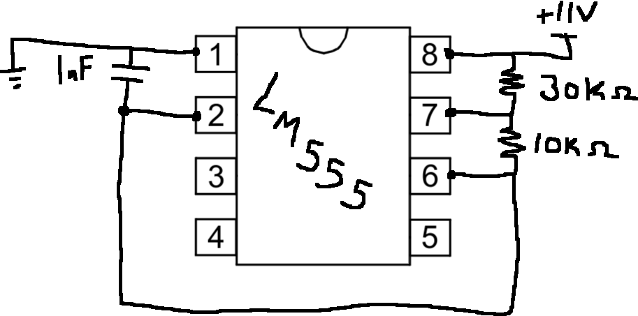
You can then measure the output on pin 3. You should see something that looks like a square wave, kind of. Answer the following questions about this wave:
Once you have that working, you can hook up pin 3 of this little circuit to the gate of your MOSFET in your buck converter. Measure the voltage across the output resistor by using two probes with their ground clips connected to the input ground, as shown below.

You should see a roughly-constant voltage across the load resistor, with some wiggling around that point. To help answer the following questions, you can use the Measurement tools on the scope to measure the Average Value (Full-screen).
2.3) Voltage Ripple
2.3.1) Effect of Capacitance
Now let's think about the effect of changing the output capacitor C_{\rm OUT}. Firstly, we can try to predict this using theory. Above, we calculated the frequency response of our circuit, and we can use that to reason about the effect of changing C_{\rm OUT} on the ripple on our output.
Although our input signal here is a square wave, we can still use our frequency response to think about how our circuit will respond to it, because we can think about decomposing a square wave into a bunch of sine waves. You should consider taking 6.300 at some point, where you'll learn more about how to think about this kind of decomposition, but for now we'll just come out and say that our square wave input, assuming a duty cycle of 78%, can be rewritten as:
Let's not worry too much about the gross math here, though; instead, here is a little animation showing how these sinusoids add up to give us the square wave (you'll need to click 'play' to start it going):
Our real question is: how do we use this to help us think about the filtering behavior of this circuit, and about how much ripple we expect to remain in our signal?
We'll do this by making a first-order approximation of that infinite sum of sine waves: we'll think about our signal as consisting of a constant offset and only one of the sine waves from the series (specifically, the k=1 term). Plugging in values, we can come up with a (very) crude approximation:
This is very approximate and will likely underestimate our actual measured ripple, but it will let us think about how our filter will affect this signal, at least to get some order-of-magnitude kinds of results.
Let's use this approximation for the next few questions.
2.3.2) Effect of Switching Frequency
2.4) Efficiency
Moving forward, let's run with C_{\rm OUT} = 1\mu{\rm F}.
What is the impact of output capacitance on ripple? What is the impact of switching frequency on ripple? What is the efficiency of your new circuit? How does this compare against
the circuit from before? How does it compare against our theoretical result?
Show your results to a staff member.
3) Comparison
So why do we care about efficiency? Well, one place we care is when we're powering a device from a battery; in short, a more efficient power converter means longer battery life! In this section, we'll put that idea to the test a little bit, using supercapacitors as little rechargable 11V batteries.
In this section, we'll use the supercapacitor "battery" to power our circuit; we'll try both power converters (our original resistor divider and the buck converter we built) to step the voltage down from the 11V we get from the supercap, and we'll compare how long each one can power the Teensy for.
Before we get rolling, download song.zip and flash it to your Teensy. This program plays a fantastic song on a little loop. It will also blink a little orange LED once every second while it is running, which you can use to estimate how long it runs for.
Once you're sure the code has been successfully flashed, DISCONNECT your computer from the Teensy.
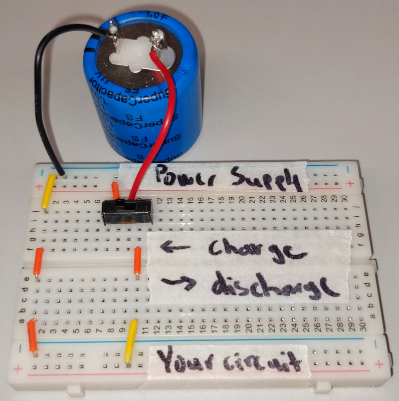
Up front, we have some little boards that we made for you to help hook things up to the battery for this experiment; they look like this:
3.1) Connecting the Test Board
The setup here is a little complicated, so let's read and follow these instructions carefully:
-
Remove the 120\Omega load resistor from both of your circuits.
-
Hook the 11V benchtop power supply up to the top two rails on the board (labeled "power supply").
-
Hook up a multimeter to measure the drop across the battery.
-
Each of the circuits you build can be thought of as having an input voltage (which was coming directly from the power supply in our earlier experiments) and an output voltage (the drop across the load). To start, we'll connect up our voltage divider circuit:
-
Use some wires to connect the spot labeled "your circuit" on the test board to the input of your voltage divider (where we had connected the power supply before).
-
Also connect the output of your divider to pins 5V and G on the Teensy.
-
-
Connect a speaker between pins 11 and G of the Teensy as well. You can plug wires into the little white connector on the speaker if you need to.
3.2) The Experiment
The testboard has a switch on it. When this switch is thrown to the left ("charge"), the battery will charge up from the benchtop power supply; when it is thrown to the right ("discharge"), it will be used to power your circuit.
So here's what we're going to do:
-
Throw the top switch to the left ("charge") and wait for the battery to charge up to 11V (when the current gets down to ~.03A or so, you're probably reasonably charged).
-
Then throw the top switch to the right ("discharge"), and the Teensy should start running.
-
Keep track of how long the Teensy runs before the battery dies, by counting the number of blinks (and/or keeping track of how far we make it through the song and/or using a stopwatch). Write that number down.
Repeat this process at least 3 times so that we get a sense of how long, on average, things run for.
Then, repeat this same process but with your buck converter instead of the voltage divider. Completely disconnect the voltage divider, then hook up the "your circuit" spot on the test board to the input of your buck converter (where we had the power supply hooked up before), and hook up the output of your buck converter (i.e., the drop across the cap) to the 5V and G pins of the Teensy.
Then charge up your battery fully and use it to power the Teensy, again counting how long it runs for. As before, repeat it a few times to get a sense of how long things run for.
When you're done, please return: Any other wires or fixed-value resistors you can just throw away.
Discuss your results with a staff member.
4) Additional Food for Thought
OK, so our buck converter was a big step up from our resistor divider. But you might still be concerned. Given the theoretical 100% efficiency we calculated, shouldn't we have been able to do better than the maybe 70-80% efficiency you found for your circuit? The short answer is that yes, there is still a lot of room for improvement here (carefully-designed buck converters can often exceed 90% efficiency). We've built a prototype, and we hope that it was fun and instructive; but if we wanted to actually try to maximize efficiency, there are a number of things we would want to do differently.
For one, we wouldn't build this circuit on a breadboard. Those little parasitic capacitances between each row of the board are problematic, as are parasitic inductances from any loopy wires sticking up from the breadboard. We would want to keep things flat to the board, but even better, we would want to lay something like this out on a PCB and avoid the breadboard altogether.
Bonus: If you want to observe the effects of this parasitic inductance and capacitance, try measuring the switch voltage (drain-to-source) while it is operating. Whoa! We see a lot of overshoot and ringing, this looks similar to some of the measurements we have seen for a series RLC circuit. Turns out you can model the effects of turning off a MOSFET with a series RLC circuit, where the L is the parasitic inductance of your circuit and C is the capacitance of your MOSFET. Here you can try and decrease the wire length you used to wire the MOSFET to the rest of the circuit and see if you can reduce this overshoot.
We could also use better components. As one example, using the 555 to generate our square wave is somewhat wasteful, and there are much better ways (though they are beyond the scope of this class).
Bonus: If you want to try and increase the efficiency of your buck converter you can try and decrease the inductor loss by placing two inductors in parallel. Or you can try changing the switching frequency by adjusting the resistors in you 555 timer. Or you can try two diodes in parallel to decrease their conduction losses. Or many other things, talk to a staff member if you want help trying out some ideas.
Buck converters also generally work best in high-power applications; for powering the Teensy, there are likely better options in the first place.
Making some of these changes, it's possible to make a much more efficient buck converter than the one we built today. If you're interested in exploring these ideas further in the future, you might be inerested to take 6.222 (Power Electronics Lab) and/or 6.622 (Power Electronics) at some point; both are classes about power electronics and likely explore some of these issues in much more detail.