The Pièce de Résistance
Please Log In for full access to the web site.
Note that this link will take you to an external site (https://shimmer.mit.edu) to authenticate, and then you will be redirected back to this page.
Your roommate has built the following circuit to serve as a filter:
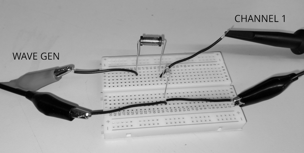
The circuit consists of a single inductor (labeled as a 32{\rm mH} inductor) and a single resistor. Your friend modeled this circuit in the following way:

Using this model, they chose R such that the -3{\rm dB} point of the filter would be at around 500Hz. Answer the following questions, using these approximations (and without using a calculator):
\pi\approx 3.1
2\pi\approx 6.2
1/\pi\approx 0.32
1/2\pi\approx 0.16
- What value of R did they use?
- With this value of R, what is the gain of this filter as f\to 0{\rm Hz}?
- With this value of R, what is the gain of this filter as f\to \infty?
When they actually hook the circuit up to the scope, however, they do not see values that agree with what you found above! Instead, they see that the gain of the filter approaches -6{\rm dB} as the frequency goes to zero!
It turns out that we can account for this if we model the inductor package as having some resistance (from the long coil of wire) as well as an inductance:

Given this measurement and your previous results, determine the value of R_L and find the frequency at which the gain of the filter will be -9{\rm dB}.
Upload your answers and work as a single PDF file, including both your answer and your
work. Please do not include any identifying information in your submission
so that we can grade the submissions anonymously.
