Digital-to-Analog Converter
Please Log In for full access to the web site.
Note that this link will take you to an external site (https://shimmer.mit.edu) to authenticate, and then you will be redirected back to this page.
As always, we have a help queue active during the lab! Go through the lab, answer the questions on this page, and ask for checkoffs on the queue! When you're all done with everything, you're done! If you get stuck on the way, let us know; we're happy to help!
Remember that labs are intended to be a learning experience, not a test, so take your time and understand things, and please ask us questions as you're working through!
Although we do want everyone to work individually and build their own circuits, it is also more than OK to ask friends/neighbors for help, too.
Table of Contents
One way that circuits demonstrate their usefulness is as transducers, converting signals from one domain (light, temperature, pressure, electrical, etc.) to another. We've seen examples of this in every lab so far; in lab 0, we were converting information about light and sound into electrical sigals, and in lab 1, we were using the joysticks and buttons to measure information about the world as well, which we then made use of in last week's lab.
In the last lab, we took an additional step of including a microcontroller and used it as an interface to take measurements about the real world and digitize them so that we could make use of them inside of a computer (to determine the position of the joystick as well as the buttons that were being pressed). This illustrates another amazingly-useful application of circuits: as interfaces between the physical world and computation.
The microcontroller makes a comeback today, where we'll use it to demonstrate conversion in the other direction: rather than using the RP2040 to measure analog voltages from the world, we'll use it to generate them.
The RP2040 is a digital electronic device, meaning that it operates using only two types of voltages: On and Off, with "On" being a high voltage and "Off" being a low voltage. In the RP2040, the "On" voltage is around 3.3 Volts and the "Off" voltage is near 0V; and, as a digital device, the RP2040 does not utilize voltages in between those values internally. However, if we're thinking about interfacing with the physical world, it is often useful to be able to work with analog voltages like the ones we've mostly seen so far in lab (which can take any value, not just "On" or "Off"). This lab will be an opportunity to explore that idea a little bit by building a 6-bit digital-to-analog converter, which will allow us to use the RP2040 to generate a more diverse set of voltages.
1) Analysis
Here's the circuit we'll be using today (which hopefully brings back some memories from past p-set problems).

Using superposition, solve for the v_\text{out}. Be prepared to talk through your work during Checkoff 1.
Enter your answer as a Python expression, using values V_1, V_2, V_3, V_4, V_5, V_6, and R, respectively, to refer to these values.
v_\text{out} =~

2) The Digital Abstraction
As mentioned in the prelab, this circuit is useful as a digital-to-analog converter (DAC, often pronounced like "dack"). We're going to hook it up to our RP2040, which is only capable of producing two voltages: a "high" voltage of 3.3 Volts and a "low" voltage of 0 Volts relative to its internal ground. Programmatically, we can set any pin to "high" or "low", making the corresponding pin look like this:
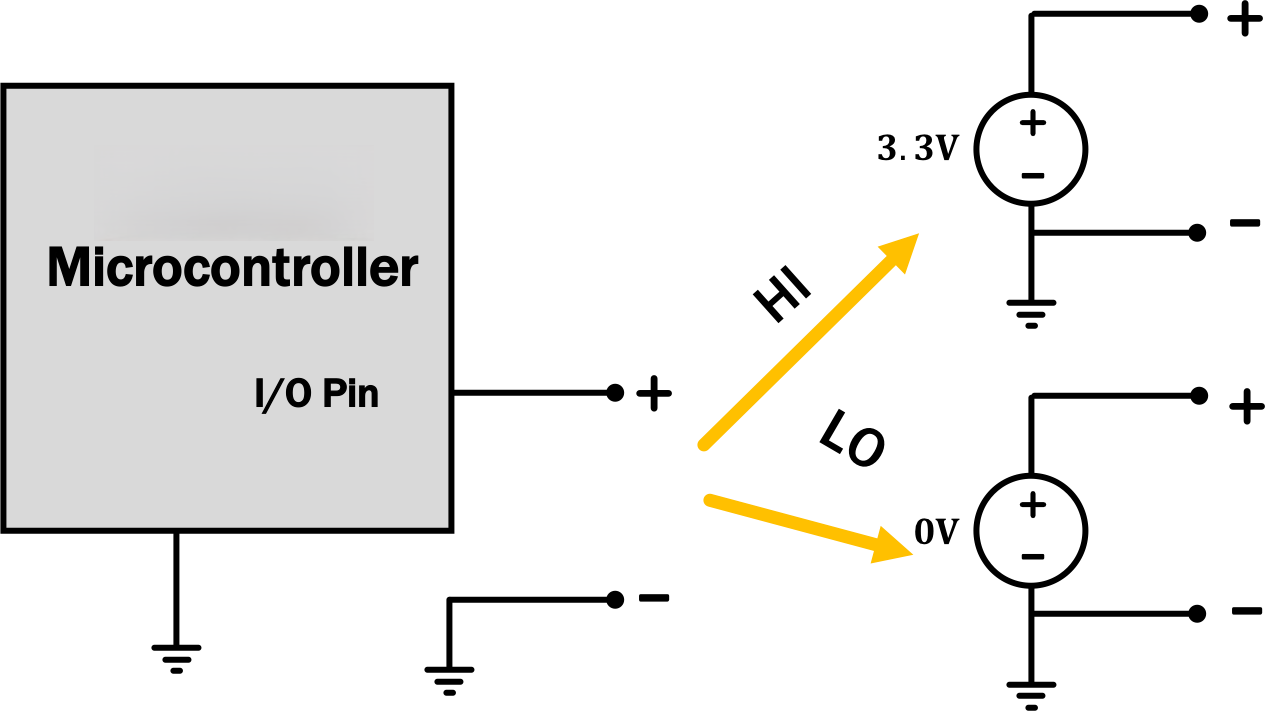
By hooking various pins of the RP2040 up to a circuit like the one at the very top of the page, we'll be able to get a much wider variety of voltages from the RP2040.
3) Grab Your Equipment
Now that we know what to expect, we're going to build the circuit from up above, using several of the RP2040's pins to provide the voltage sources indicated there.
Since it takes a while to boot up, turn on your scope before going to grab your parts so that it can be warming up while you're grabbing things. Then grab a RP2040, a breadboard, and a speaker. We'll also need to cut some wires, so grab yourself some clippers as well.
For this lab, grab a full-sized breadboard since the circuit we're going to be building is pretty big (especially if you decide to try some of the optional pieces at the end).
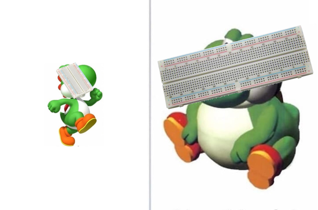
|
|
| not the little one with 30 rows. |
the BIG one with 60 rows. |
When using the RP2040 with a breadboard, it's best to plug it in on the very end of the board so that it's spanning the gap in the board, with its USB jack facing outward; like so:
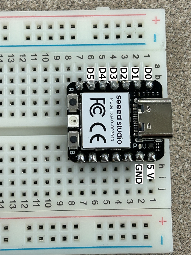
It can take some work to get it into the breadboard. Be careful not to break things, but it's OK to use a little bit of force to get the pins to go in.
Note, you do not need to provide external power to the RP2040, your computer will provide the power through the USB cable.
Once you've done that, construct the circuit from the very top of the page, using pins D0, D1, D2, D3, D4, and D5 to provide V_1, V_2, V_3, V_4, V_5, and V_6, respectively. Use a value for of 1{\rm k}\Omega for R when building your circuit.
As we build more complicated circuits in lab, the layout of your breadboard becomes more important. In particular, the nicer you layout the circuit the easier it is to troubleshoot (both for yourself and when you ask for help from the staff). So taking the time to layout your circuit clearly will save you time in the long run.
As a layout tip, it is good to try to make the structure of this circuit on your breadboard somewhat match the structure of the schematic, if possible. Specifically, we recommend having the 2R resistors cross the center gap in the breadboard, with two open holes between each one (which makes connecting them via R resistors easy); and having the v_{\rm out} side of the circuit be on the side of the RP2040 (i.e., having V_1 close to the RP2040 and V_6 farther away).
We also have some little pre-cut wires in the bottom row of the resistor cabinet; the orange ones are conveniently-sized for jumping across the center gap of the breadboard or from the middle part of the breadboard to the closer of the red/blue rails; and the yellow ones work for jumping from the middle part of the board to the farther one of the red/blue rails. You should, of course, feel free to cut your own wires; but the little pre-cut ones are often super convenient.
Lastly, it might be helpful to cut the legs of your resistors to they sit closer to the breadboard. When the legs are long it is easier to accidentally short them together causing issues in wiring.
We're happy to consult on board layout as well; just ask!
Also note that the pin labeled "GND" in the very corner of the board is the RP2040's internal reference. The "-" sides of the voltage sources in the circuit above are all connected to that spot internally by the RP2040 (as shown below), so there are some other components we'll need to connect there as well to complete the circuit.

A partial view of a model of the RP2040's internals
G). How can we adjust the schematic from up above to account for this fact? Where and how should we wire up the RP2040's pin G? What components should it connect to?
We're going to use a couple of different programs to test things today. You can download them all as a ZIP file: dac_code.zip.
Make sure to extract the files from the zip archive before proceeding.
To start, we're going to use the program called "stepper"
(stepper/stepper.ino inside of that ZIP file), which you should flash to your
RP2040 using a similar process to what we did last week:
- Open Arduino and open
stepper/stepper.ino. - From the menu, under
Tools\toBoard: ..., selectSeeed XIAO RP2040. This tells Arduino what kind of board we're programming. - Plug your RP2040 into the computer via USB cable (we have extras if you need one).
- From the mentu, under
Tools\toPort: ..., select the port you are connected to (if you can't figure out which one, unplug the RP2040 and see which port option disapears.) - Click the second button from the left in the Arduino window, which looks like a rightward-pointing arrow (it should say "Upload" when you hover over it). This should compile things and send the result to the RP2040 with no orange error messages.
If you use channel 1 on the scope to measure v_\text{out}, you should see what looks like a little ramp repeating itself every so often (you'll likely need to zoom in/out to get a clear view of it). Make sure to turn on "BW Limit" so things aren't too fuzzy. If you zoom in closely, you can see that it's not actually a smooth ramp, though; it's got lots of little sements in it if you zoom in enough. You may also wish (for now) to set a trigger in the middle of the ramp or something like that, and switch the trigger to Normal mode (which should help hold things in place). Or you can use the Run/Stop button manually to freeze things on the screen.
Given those measurements, how many distinct steps are there in the ramp? Be prepared to talk about these measurements and how you made them during your
checkoff.
Discuss your results so far with a staff member. How
did you solve for the values in the circuit at the top of the page? Do your
experimental results match the theory?
4) A Second Program
Now load the "song" program (song/song.ino in the ZIP file) and continue
measuring the output. Hit "Default Setup" and then use the controls on the
scope to get a nice view of the output wave (we want the wave to be taking up
most of the screen). If you had your trigger in Normal mode for measuring
the ramp, switch it back to Auto.
Now, let's listen to it by hooking up a speaker across the port labeled v_{\rm out} in the diagram. You should hear a song. But oh, no! It's really quiet, way quieter than the ~2.2 volts we were measuring should be. And indeed, look at the scope!!! What changed about your signal?
Let's see if we can understand this change using circuit theory. But oh, no!
The DAC is a complicated circuit with six independently-controllable voltage
sources and thirteen resistors, so solving that seems like kind of a pain.
 . It wasn't too bad to analyze using series/parallel combinations and
divider relationships, but still...it sure would be nice if we could model it
as a simpler circuit instead...
. It wasn't too bad to analyze using series/parallel combinations and
divider relationships, but still...it sure would be nice if we could model it
as a simpler circuit instead...
...wouldn't it?
...
...
Thankfully, as we've seen over the past week or so, we do have a way to do this! We can model our whole DAC circuit (including the RP2040) with a Thévenin equivalent!
By thinking about the Thévenin equivalent of our DAC, we can model our
circuit, with and without the speaker connected, as shown below; much nicer to
analyze with way fewer components! Yay! 


|

|
| without speaker | with speaker |
Now, let's make some measurements and see if we can empirically determine the
Thévenin resistance of our DAC circuit. Firstly, let's switch back to
the stepper.ino program on our RP2040. Then, use the scope to answer the
following two questions:
- What is the peak voltage of the stepper program without the speaker connected?
- What is the peak voltage of the stepper program with the speaker connected?
Note that you may need to zoom way in to make this second measurement, and if the ramp looks really fuzzy, you'll want to measure in the middle of that fuzz, not on top of it (and make sure that "BW Limit" it on to reduce the fuzz in the first place!).
R_{\rm TH}\approx~
Be ready to talk through your math during the checkoff.
Discuss your results with a staff member. How did you
calculate R_\text{TH} using the scope measurements? How did you solve it
using theory? Demonstrate the song playing as well.
5) Op-Amp to the Rescue
In this section, we will be using your DAC with an additional component at the output. DO NOT DISASSEMBLE YOUR DAC.
In the previous section, we saw the impact of the speaker loading the circuit. This is because our circuits aren't modular (i.e., as we add components, it effects the overall operation of the entire circuit).
For today, let's get a look at a component that we can model as a dependent source, which will let us resolve the issue from the previous section. The specific component we'll use today is called an operational amplifier (or "op-amp" for short). We'll be spending a lot of time with op-amps a few weeks from now, but for today we'll take a look at one possible way we can use them: isolating different parts of a circuit from one another.
Ultimately, the way we're going to hook up the op-amp today will allow us to model it as a voltage-controlled voltage source with a gain of 2 (i.e., a VCVS whose output voltage is twice its input voltage):

We can use this VCVS to prevent the loading problem we saw when we connected our speaker to our DAC, like so:

Op-amps are amazing things that can be used for a variety of different purposes, and we'll spend a lot of time working with them in the near future; but for today we'll focus on hooking it up so that it acts like the VCVS described above (whose output voltage is double its input voltage).
Today we will be using a L272 op-amp, which you can grab from the front of the room.
Go ahead and grab an L272 from the front of the room and position it in your breadboard, like this. DO NOT DISASSEMBLE YOUR DAC, just put this on the breadboard too, or grab another breadboard if you are out of room.
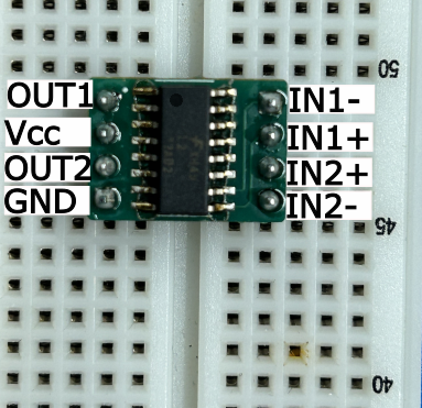
Note that there is a little dot (a white one on the PCB and one on the op-amp chip itself) that marks which pin is the output, so you can use that to orient things properly.
To make this happen, we'll need to make the following direct connections:
- The
5Vpin from the RP2040 to theVCCpin of the op-amp - The
GNDpin from the RP2040 to theGNDpin of the op-amp - The output of your DAC to the
IN1+pin on the op-amp
Then we'll also want to connect:
- a 1k\Omega resistor between
IN1-on the op-amp andGNDon the op-amp/RP2040, and - a 1k\Omega resistor between
IN1-on the op-amp andOUT1on the op-amp.

After having done so, we can measure our output voltage v_{\rm out} between
pins OUT1 and GND of the op-amp.
Set up channel 1 to measure the output of your DAC (the same place you were measuring before), and channel 2 to measure the output of the op-amp. How do these signals relate to each other?
Now go ahead and try to play the song (switch back song.ino), and put the
speaker between OUT1 on the op-amp and GND. It should sound a little better
than before :)
While the song is playing, try disconnecting and reconnecting the speaker and seeing how the signals change.
Please clean up. Return the speaker, op-amp, and cables to the front. DON'T DESTROY YOUR DAC, THOUGH!!! We're going to use the DAC in a couple of labs in the future. If you want to
leave it in the lab, put some masking tape on the back and write your Kerberos
username or something on it so you can find it, then put it in on the shelves
by the doors in 34-501. PLEASE RETURN USB CABLES AND SPEAKERS, THOUGH. Otherwise your friends in
the other lab sections might get upset when we don't have enough to go around. Have a good weekend!
Discuss your results with a staff member. What is a VCVS? Why does adding a VCVS fix our challenge with the speaker from the last checkoff? Where does the power for the speaker come from?
6) More (Optional) Fun Things To Do If You Want To
None of the stuff here has a checkoff or affects your grade or anything like that, but if you're having fun, there are some other things you might explore:-
Try changing the rate at which we move through the samples in the
song.inofile. What happens if you speed it up by a factor of two? What if you slow it down by a factor of 2? -
Try using the RP2040's input pins to detect button presses and use those to change the frequency of a sine wave (the
sine/sine.inoprogram can be a good starting point), making yourself a little musical instrument. Or, measure the (continuous) voltage from a potentiometer hooked up as a voltage divider and using that voltage to control the frequency of a sine wave so that you can smoothly go between different frequencies. -
If you want to, we also have a way for you to load your own tunes onto the RP2040. You can use this site to convert a portion of a youtube video to the right format for this lab, which you can download and then reflash to the RP2040!
If you do try these things (or other experiments of your own), we'd love to see what you come up with! :)