Gamepad
Please Log In for full access to the web site.
Note that this link will take you to an external site (https://shimmer.mit.edu) to authenticate, and then you will be redirected back to this page.
If you haven't done the this link and take the EHS00509w Electrical Safety Awareness course, you must do it before starting this lab. To do this, search for "509" under the Course Catalog Page, which should find the "Electrical Safety Awareness" course.
Table of Contents
1) Reminder: Soldering 101
To start, take a look back at the prelab exercise which presents an introduction to soldering to remind yourself of the general process and review the safety information there.
There is also an unedited video of the whole process of building today's board here. Throughout the lab writeup, we'll provide links to the relevant parts of the video.
2) Safety First
Grab safety goggles and wear them whenever you or someone near you is soldering or clipping wires (i.e., basicaly the whole time we're in lab today).
If you want a vent fan, go ahead and set one of those up as well! This is generally not necessary for most people, but if you have an existing respiratory condition (e.g., asthma), it might not be a bad idea to grab one.
If you have long hair, it's probably a good idea to tie it up as well if you can (or just make sure to keep it away from the hot part of the iron). We have extra hair ties if you want.
3) Brief Overview
Today, we'll be making a pretty cool project, I think: a USB gamepad that can be used as a video game controller (it should be recognized by most games as a Playstation 4 controller):
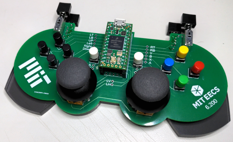
This one was built on a green PCB, but we have a bunch of other colors available, too, so go ahead and pick whatever color speaks to you. They're all functionally the same; they just look different.
We'll be adding the components to the board, and the PCB connects them to each other. Before we move on to actually building the board, let's remind ourselves of how things are connected up.
3.1) Setting Up
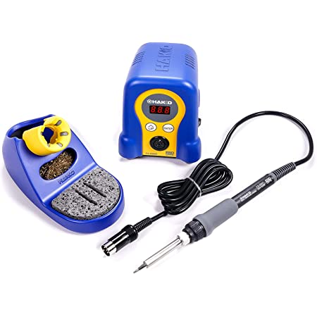
Start by turning on the soldering iron (the switch on the right-hand side of the base) and adjusting its temperature to around 750. If it's not already set at 750, hold the "Enter" button and then you should be able to use the arrows to adjust the temp. until the left-most number starts flashing.
Also if the sponge on your iron isn't damp, we have some water bottles we can use to dampen it. It shouldn't be dripping wet, but just a little damp. You can use that (and the little gold-colored abrasive metal thingy in the soldering iron stand) to clean excess solder off the tip of the iron.
There should be some solder already at your table, but you can always go back for more if you need). If you do need more, you don't need to use wire cutters or anything like that; you can just use your hands to tear off a length of solder.
3.2) Initial Prep: Adding Pins to the RP2040 Board
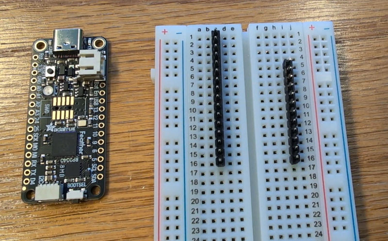
We'll be using the same microcontroller for this lab that we saw on the first problem set, but in a slightly different form factor. The boards come to us without pins soldered to them, so a good starting point for this lab is to start by soldering the pin-to-pin headers to the microcontroller. It is really important that these go on straight, so to start, plug the headers into a breadboard (the side with the longer pins should be going into the breadboard).
Plug the 16-pin headers into one side of the breadboard and the 12-pin headers into the other side, spaced out like so:
Then you should be able to set the RP2040 board down so that all of the pins poke through (if not, double-check that you got the spacing right):
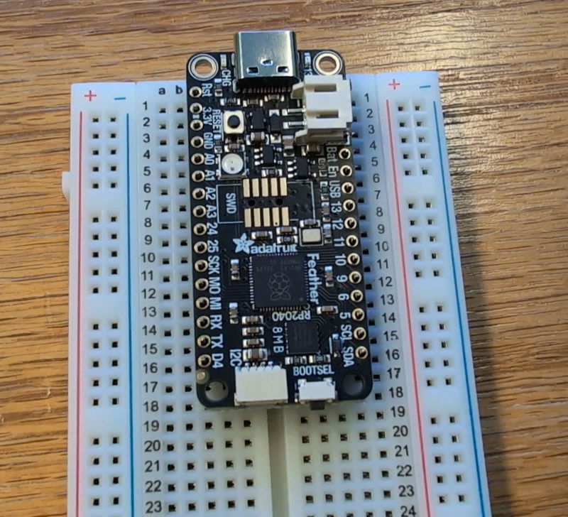
Make sure the board is sitting flat and level before soldering.
Once you've done that, it's time to solder these pins in place. Hold the iron in your dominant hand and rest it so that it's making contact with both the pad (the exposed metal on the board) and the pin sticking through. Please be careful that your iron doesn't make contact with any of the other components on the board!
Then you can go in and solder all of the pins (though it might be a good idea to start with the four corners instead of going down the row like I did):
Creating a solder joint involves a few steps:
- Heat both the pin (the piece of metal sticking through) and the pad (the little circular metal contact on the PCB) for 2-3 seconds using the iron, making sure it's in contact with both.
- Feed a small amount of solder onto the joint. It should "flow" smoothly onto the pad and make a shape like a little cone.
- Continue heating for another second or so, then remove the iron.
- Let the joint cool before moving things around (you should see it change color slightly when it's cooled enough to be mechanically stable).
Here is an example of a solder joint:
And here are some examples of bad solder joints (what to look out for as you're working):
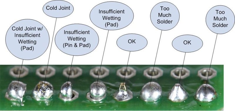
If you do make a mistake, that's OK; we can usually fix it with a little bit of effort. This page from Adafruit discusses how to fix them, or feel free to ask us for help!
If you want us to demonstrate and/or to take a look at your work as you're going, just let us know! We're happy to help.
Now, remove the RP2040 board from the breadboard but please do so CAREFULLY. You can kind of rock it back and forth a bit to avoid bending the pins.
3.3) Buttons
Now that the microcontroller is ready, the first component we'll look at actually adding to our controller is a button (momentary switch) like the ones we saw in last week's lab. In a circuit schematic, we'll often draw a momentary switch like so:

While the button is pressed down, its terminals are shorted together; but when we let go of the button, its terminals are again disconnected.
Each button is connected like this, with the 3.3 Volts being provided by the RP2040 microcontroller:

The red "+" and "-" tags there represent a place where the R2040 is set up to measure voltages. By measuring those voltages, we can detect when a button is pressed/released.

In the controller, the RP2040 will measure these voltages to detect whether a given button is pressed or not.
4) Adding the Buttons to the PCB
Now that we understand how the buttons should work, let's go ahead and solder them to the PCB. We'll also eventually go ahead and connect the RP2040, which we can then use to test that the buttons are working correctly.
Now that we've seen how everything is connected up, let's move ahead with building the circuit.
4.1) Shoulder Buttons
For now, to keep things moving, just grab four of the little silver shoulder buttons and a PCB (whatever color you want); grab the other pieces as you need them.
The first things we'll add to the board are the four "shoulder" buttons on the top of the board (chosen to go first because they are physically the shortest components).
We'll actually start with the two that sit on the back of the board. Stick them into the board like so, putting the five pins of each through the five holes they fit into. Make sure the buttons themselves are on the side of the PCB with no text/logos on it (the pins should stick through the front side).
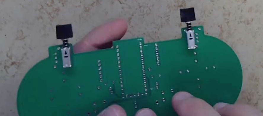
Now, flip the board over and let gravity hold things in place while you solder the pins.
Adding the back shoulder buttons is shown at this point in the demo video.
4.2) More Shoulder Buttons
Then do the other shoulder buttons (the ones that sit on the front of the board). Stick the pins through so they're sticking out the back, then flip the board over and solder the pins in.
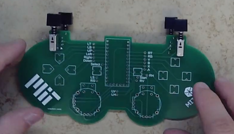
Adding the front shoulder buttons is shown at this point in the demo video.
4.3) Other Buttons
Next, we'll add the other push-buttons. I usually do these in little groups of four (start with the four on the right, then do the four on the left, then the two in the middle). But you it might be easier and/or more efficient to do one at a time instead.
However many you decide to set up at a time, feed the buttons' leads into the associated holes on the board, flip it over, and solder one pin in place. Flipping the board with all of the buttons in can be a little bit hard, but you can use a piece of paper like we did in the demo video to help keep things in place. We have some spare paper on the tables at the front of the room if you want some. Just make sure you move it away from the iron when you start soldering.
Adding these buttons is shown at this point in the demo video.
You'll want to provide some downward force on the PCB while you're soldering so that the buttons sit flush with the surface of the board. Double-check afterwards. If the buttons aren't flush with the PCB, they can easily break off.
Once they're all sitting flush against the PCB, you can go in and solder the other pin on each button in place.
 OH NO Button not flush with the PCB surface!
|
 Much better!
|
If yours aren't flush, that's OK; you can often fix it by melting the solder again and pushing the leads farther through the hole while it's melted. And again, if you need help, just let us know!
4.4) Double-check!
Double-check all of your connections, and double-check that your buttons are sitting flat against the PCB.
4.5) RP2040 Socket
Next, we'll add a place for our RP2040 board to live. Do not solder the RP2040's pins directly to the board. Instead, we'll make a socket for it by connecting up some headers like so (the black part should be on the side of the board with the words printed on it):
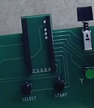
Plug those in to the board and then plug the RP2040 into them (this will help to keep them aligned with the board).
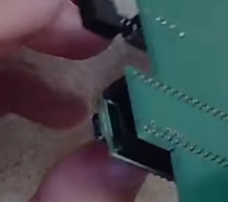
Then:
- Flip the board over again.
- Solder 4-8 pins near the corners.
- Remove the RP2040 and set it to the side for now.
- Solder the rest of the pins.
Adding the RP2040 socket is shown at this point in the demo video.
4.6) Test It!
Now that you can plug the RP2040 in, we can use it to test the connections
we've made so far. We're going to make all of our measurements relative to
the connections labeled GND on the controller PCB. In order to give us an
easy place to grab on with the multimeter/scope clips, we're going to use a
'test point.' You can grab two of these from up front and slide one into the spot
labeled GND like so, so that the side that's a solid loop is on the top side of the board and the other side is poking through (DO NOT solder this in place):
That should give a place to grab onto with your alligator clips. Then we'll need to flash some code to the RP2040 to set us up to measure. Please follow these steps carefully:
- Hold down the small button on the board labeled "BOOTSEL" and connect it to your computer via USB cable.
- Download gamepad.zip and extract its contents somewhere.
- Open up
gamepad.inoin Arduino IDE - On the left-hand menu, look for the icon that kind of looks like books on a bookshelf ("Library Manager") and open that.
- Search for "tinyusb" and you should see a result from "Adafruit TinyUSB Library."
- Click "Install" beneath that and wait for it to go.
- From the top menu, choose:
- Tools -> Board -> Raspberry Pi Pico/RP2350/RP2040 -> Adafruit Feather RP2040
- Tools -> Port -> UF2 Board
- Tools -> USB Stack -> Adafruit TinyUSB
- Click the little right-facing arrow icon to compile the code and flash the result to the board.
With that done, let's use the scope to make some measurements to make sure things are changing as expected as we push the buttons. If your scope doesn't have probes already, you can grab one from the front of the room (or ask a staff member if you're having trouble finding one).
Connect the alligator clip of the scope probe to the test point you connected
to GND, and plug another test point into the spot labeled "△" so that you can
clip the + side of your scope probe there. Then, pressing the corresponding
button should cause the measured signal to change. You can then repeat this
process, moving the little test point around to test each of the buttons one by
one. Do they change as predicted by the theory above?
Test all of the buttons except LV, LH, L3, RV, RH, and R3 (which
come from the joysticks that we haven't added yet) and make sure they change as
you expect when you push the buttons.
Once you've received your checkoff and are absolutely sure that things are
working as expected, you can use wire cutters to trim off the excess pins on
the buttons so that we don't have those long wires sticking out. When clipping, use another finger to hold the pin so it doesn't go flying when
you cut it; and WEAR GOGGLES WHEN DOING THIS;
little metal clippies flying out and getting stuck in your eyes is not much fun. Also unplug your RP2040 from the socket on the board until we're ready to
test again.
Show your work so far to a staff member.
4.7) Joysticks
In last week's lab, we learned about potentiometers: three-terminal devices that we can think of as containing two resistors that we can change by turning a knob or similar.
The joysticks we'll use are actually the same joysticks that are used in real PlayStation 4 controllers (maybe also PlayStation 5; I'm not sure...), which is kind of cool.
Each joystick contains two potentiometers (one whose \alpha value changes from 0 to 1 as the stick moves left-to-right, and one for up-and-down).
Go ahead and grab a joystick from the tables at the front of the room. They look like this, where the two little orange thingies on the sides are the potentiometers. Each pot has three terminals, which are connected like so:
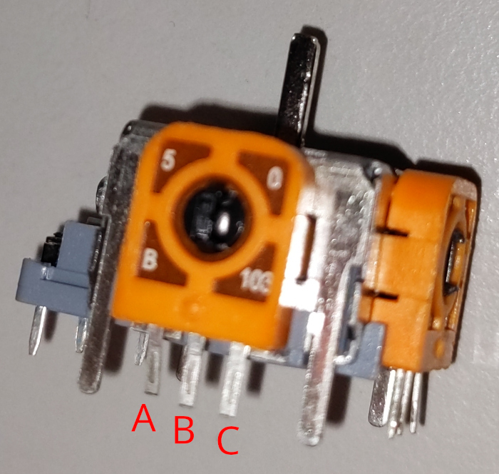

In the controller, we'll use these joysticks as voltage dividers by dropping a voltage across the two internal resistors. The voltage source shown here will be provided by the RP2040, which provides a constant 3.3 Volts. Each pot within the joystick is connected like shown below, where the RP2040 is set up to measure the voltage between "+" and "-" for each:

R_P and/or alpha, which represent the variables R_P and \alpha, respectively.
We'll set up the RP2040 to measure this voltage for each direciton, which we can use to find the (x, y) position of the joystick.
4.8) Adding the Joysticks
So let's go ahead and add the joysticks to the board. We recommend doing them one at a time. For each, like all the other pieces, we'll feed the pins through the board so that the physical body of the joystick is on the side with the words and logos and whatnot:
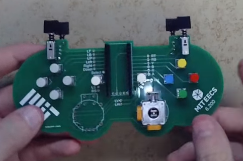
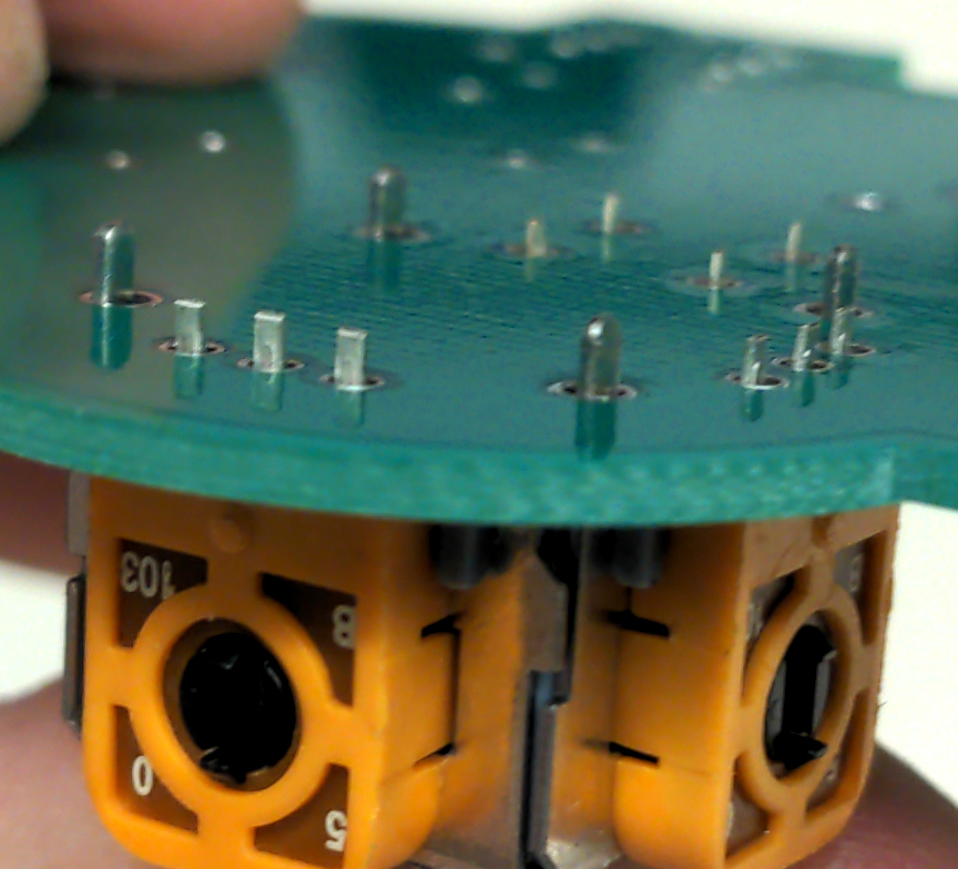
BUT BE REALLY REALLY CAREFUL! It can be hard to get the pins to line up correctly, and we want to make sure we're not forcing anything (the joysticks themselves can break). A good place to start is to make sure all the pins are straight. And even then, it can take some time to get things to line up. When things are set up appropriately, you should be able to see all of the pins sticking out the back side of the board, like shown in the following image. There should be:
- two sets of three pins, one for each potentiometer (six total)
- one set of four small pins for the button
- four large pins on the side (not electrically connected, just there for mechanical support)
for a total of 14 pins per joystick. All of these should be clearly visible before you start soldering, like so:
A good way to start is by holding the joystick flush with the board while you solder one of the pins; this should then keep it in place while you solder the rest. You can also use a piece of masking tape on top of the joystick to hold it flush with the board if that's helpful.
Once you've got all the pins visible, go ahead and solder them. Be careful with these ones, since they are a little difficult and a little close together. Also, the physical mechanism of the joystick can make it a little bit tricky to keep things straight. Take your time and be careful, and generally don't attach the cover of the joystick while you're doing this (you can do that after the soldering is done).
Adding one joystick is shown at this point in the demo video and the other is here.
Once you have them in place, you can go ahead and put the caps on the joysticks.
5) Test
Now let's test that those are connected up properly. Reconnect the RP2040 now (but don't hold down BOOTSEL this time). With the RP2040 plugged in (and running the same code from when we tested the buttons), we can make some measurements.
Remember that the joysticks each have two potentiometers inside, and we've
hooked them up as voltage dividers. As such, if we measure at LH and LV
relative to ground (the vertical stick coming out of the RP2040), we should see
changes as we move the left stick around (same for the right stick with RH
and RV). Measure LH, RH, LV, and RV and make sure they're changing as you expect.
It turns out that this is precisely what goes on if you've ever used a real game controller. The analog sticks are connected as voltage dividers like this, and the voltages are read into a computer to determine the player's inputs. Yet another cool example of circuits serving as an interface to the physical world (in this case, enabling a neat kind of human-computer interaction).
The joysticks also contain two additional buttons, which you can press by
clicking the stick down into the board. Use the R3 and L3 test points to
check that these are also working as expected.
Demonstrate your results to a staff member.
6) Using the Controller
Before we finish up (which will make accessing these solder joints a bit harder), we're going to want to make sure everything is working.
6.1) Try It!
Now let's test and see whether everything is working. We have a few computers around the room you can use to test your controller, either by playing a game or by using Steam's controller tester. Or you can test on your own machine if you want (though be aware that not all games will recognize the controller properly).
Demonstrate your working game controller to a staff member. When you're done with that:
7) Finalizing the Gamepad
To finalize things, we'll do away with the sharp edges on the back of the board and cover it with a piece of acrylic that we cut on the laser cutter next door, to make it a little less painful to hold.
First, some of the acrylic has a little bit of brownish adhesive paper stuck to one side of it. You can remove that if you want, or you can leave it, whichever you prefer; the world is your oyster.
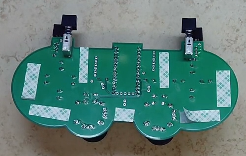
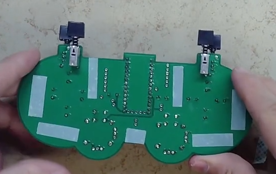
Use some double-sided tape to attach the acrylic to the back. The holes should line up with the solder joints. Grab yourself a little strip of tape and then attach pieces to the board.
You can stick the tape down like so (it doesn't have to be in exactly these spots):
then pull the backing off and stick down the acrylic to it:
Push down hard to make sure everything is attached.
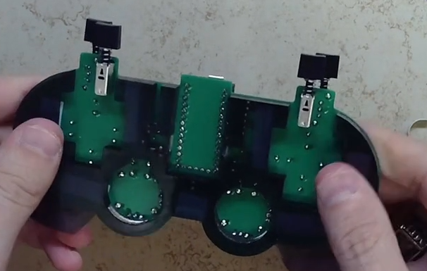
Adding the acrylic backing is shown in this video.
8) Clean Up
Woo-hoo, we're all done! The gamepad (including the RP2040) is yours to keep.
Before you leave, though, clean up by doing the following:
- Turn off your iron (and vent fan if you had one).
- Put the safety goggles back.
- It's also not a bad idea to wash your hands (there are restrooms nearby, in the elevator lobby outside the room).