Metal Detector
Please Log In for full access to the web site.
Note that this link will take you to an external site (https://shimmer.mit.edu) to authenticate, and then you will be redirected back to this page.
In today's lab, we'll be building a simple metal detector using the ideas we've been discussing in class for the past few weeks. This system will detect the presence of ferrous metal near a sensor. Here is an example of the system we'll be building today, detecting the presence of a pair of wire clippers as they pass over the sensor (notice how the LED lights up when they clippers are right over top of the sensor):
1) To Everything There Is A Season
The sensor that this system uses is not a piece of magic; it's nothing more than a simple inductor! For today, we'll wind our own air-core inductor. Using Wheeler's formula for inductance, the inductance of our air-core inductor is approximately given by:
where
- L is the self-inductance (in microHenries)
- r is the radius of our core (in meters)
- h is the height of the core (in meters)
- N is the number of turns
Ultimately, our coil will look something like this:
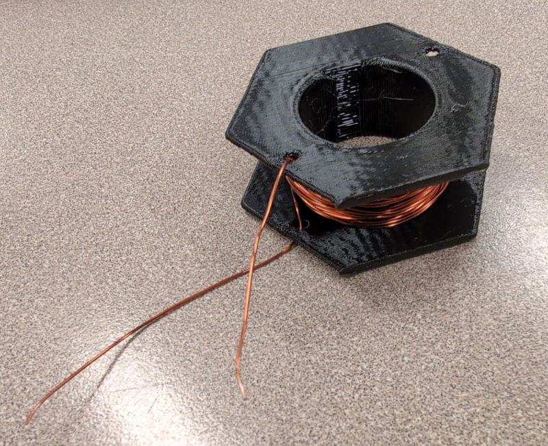
For today's inductor we are going to use a 3D-printed bobbin. The height of the bobbin is about 14mm, and the diameter of the part we'll wrap the wire around is about 30mm.

Go ahead and grab some magnet wire and safety glasses from the front. Note, the magnet wire has been pre-cut to approximately the right length and the ends have already been stripped so we can more easily connect to them. So do not cut the magnet wire!
There are strain relief holes on the bobbin to thread the ends of the magnet wire through to hold them in place as you wind the inductor. Make sure you have an inch or two of extra wire on the end as you start winding so that we can connect up to our circuit in the next section.
As you wind your inductor, wear safety glasses and be aware of where the ends of your magnet wire is pointing (i.e. don't let it poke your neighbor). Be sure to keep track of the number of turns and try to make the turns as neat as possible; it will be necessary to have multiple layers, but try your best to make your coil have uniform thickness all the way from one side of the bobbin to the other (like don't have all the wire toward the middle of the bobbin).
Show a staff member your inductor!
2) Inductor Characterization
Now, we want to characterize our inductor to see how "good" of an inductor we made. To do this, let's set up a voltage step and measure the response across the inductor.
It's a little tricky to make a real voltage step, but we'll be able to approximate it using a MOSFET (Metal-Oxide-Semiconductor Field-Effect Transistor). MOSFETs have many, many, many uses, but in today's lab we are going to use our MOSFET as a switch that we can open and close electrically.
The mosfet has three terminals: the "source" (S), the "drain" (D), and the "gate" (G). The way we'll be using things today, we can think about its behavior as follows:
-
When the voltage on the gate (G) is sufficiently high, the branch between the source (S) and drain (D) behaves approximately like a short.
-
When the voltage on the gate is low, the branch between the source and drain instead behaves approximately like an open.
As such, it's kind of like an electically-controlled switch: by applying a sufficiently high voltage to the gate, we can close the switch; and if we let the gate voltage drop low instead, we can open the switch.
Go ahead and grab a MOSFET and 10\Omega power resistor from the front of the room. These power resistors are a bit bigger than our typical resistors and can handle higher power dissipation without lighting on fire.
To start, put your inductor to the side and build the circuit below:

We'll use the benchtop power supply (set to 3.3V and a max of 1A current) to act as the 3.3-Volt source, and we'll use the wave generator on the oscilloscope to provide V_{\rm sq} (the voltage on the gate of the MOSFET, which controls whether it acts like an open or a short).
We'll configure the wave gen to produce a square waveform with a high voltage of 5V, a low voltage of 0V, a frequency of 500Hz, and a duty cycle of 10%. Go ahead and configure those things now, but we'll want to build the circuit with the power off before turning it on.
The MOSFETs we're using should fit right into the breadboard (make sure not to short the MOSFET by placing all the pins in the same column!). Along with lots of other useful information, their datasheet will tell you which pin is which (if you have trouble finding it, let us know). In this type of MOSFET, the D stands for drain, S for Source and G for Gate.
- While the gate of the MOSFET is marked with a G, that does not mean you should connect it to ground, it should be connected to the positive of the wave gen.
Try not to bend the pins of the MOSFET as you put it in the breadboard! The usual trick is to push down gently while wiggling it side-to-side, like so:
Also, be careful when you turn the power on because things can get a little hot (particularly if something is wired incorrectly).
Use one oscilloscope probe to measure the voltage across the drain-to-source of the MOSFET and another probe to measure the wave gen.
What do you see on the scope? Does it match what you expect?
Now, let's add in our inductor. You can use the little grabby thingies from the front of the room to attach your coil to the rest of your circuit. Plug the pin end into your breadboard at the appropriate spot, and then use the grabby end to clip onto your coil, like so:
Make sure to grab onto the shiny part at the end of the wire that has been sanded off (the wire has a coating on it so we won't be able to grab just anywhere).
Here is the circuit we are going to build:

What we want to measure here is the drop across your inductor. Set up the scope probes to measure the drop across your coil. As with last week, we'll need to use math mode for this. So set up channel 1 to measure the drop between the top node of your coil and ground, and channel 2 to measure the drop between the bottom node of your coil (the drain of the MOSFET) and ground. Then use the math stuff on the scope to compute the difference of those two signals.
As before, you'll want to zoom around on channel 1 and 2 so that their signals are as big as possible on the screen vertically without clipping, so that our subtraction comes out nice and clean.
There's a lot going on in this waveform, but with the way we're handling things here, we've set up the wave gen such that the MOSFET switch looks like an open for most of the time, then we close it for a brief period, then open it again.
We'll want to focus our attention on the small portion of time where the switch is closed (i.e., when the wave gen is putting out 5V, and, thus, when the inductor is charging up). That portion should be 200\museconds long, so verify that on the scope.
Look at the inductor's voltage over that region of time. Does it make sense given our circuit topology? You'll be expected to discuss the shape of this curve during your checkoff, so make sure you understand it and can tie it back to circuit theory!
Oh, well, wait. One thing that doesn't match our theory expectation is the value that the inductor voltage settles down to during that region of time.
The difference between these two measurements can be explained by expanding our model of the coil a little bit. While it is indeed intended to act as an inductor (and it largely does), by virtue of being a long piece of wire, it also has some resistance. So a better model of our coil might be like this, with a resistor in series with the inductor:

Now that we have a sense of R_{\rm L}, we can also estimate the inductance of our coil, L. Similarly to what we did last week, we'll use the scope's measurements to estimate the time constant. We can make our scope do a useful measurement for us by auto-measuring the "fall time". This is similar to the 10-to-90 'rise time' we looked at last week, but for discharging instead.
That fall time t_f relates to the time constant in a similar way to what we found last week: \tau = t_f/\ln(9) \approx t_f/2.2.
R_L and the numeric values in the circuit, and enter your answer in units of ohms. You may use par(x, y) to express a parallel combination of resistances and + to express a series combination of resistances. Enter an exact answer in terms of the values in the circuit.
R =~
Talk to a staff member about how you performed your characterization.
2.1) Metal Detector
Now that we know some things about our inductor, let's put it all together to build our metal detector! We don't actually have to do a whole lot of work to turn this into a metal detector, because the mere presence of ferrous metal nearby will change the inductance of our coil, in a way that we can detect!
You can experiment with this with your scope. Try bringing the metal end of your wire strippers toward the top of the coil (they'll need to get pretty close to make a noticeable difference here). Try putting them inside the coil. What happens, and why?
The last thing we'll do today is to use our old friend the RP2040 to measure those changes in inductance. To start, let's disconnect your scope probes from the circuit (but leave the wave gen in there), and turn off both the wave gen and the power supply while we make some changes to the circuit.
The code for today (metaldetect.ino) contains some code that measures something kind of like (but not identical to) the fall time we saw on the scope.
Go ahead and download that code and flash it to the RP2040. As a reminder, here is its pinout:
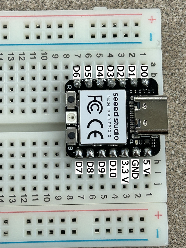
We're going to want to hook up:
- pin
D0to the top side of your inductor (where it connects to the 10\Omega resistor), and - pin
GNDto the bottom side of the wave gen and your 3.3-Volt source.
Only once you're confident everything is hooked up correctly (feel free to check with us if you're unsure!), leave the RP2040 connected to your computer and turn the power supply and the wave gen back on.
If you look at the serial monitor and/or the serial plotter, you should see the RP2040's measurement of how quickly the inductor is charging up. It's in units of microseconds, but this measurement isn't easily calculable in terms of t_f or \tau, but it should change in proportion to those things.
Try putting the wire clippers near the coil again. If you bring them close enough, you should see this value change (and it should change more dramatically if you put them inside the coil).
Ultimately, we're going to use a threshold value in the code to decide whether
there's metal nearby or not, and this threshold is adjustable by changing the
variable called threshold in today's code. When the measured charge time
is above our threshold, we'll light up an LED to indicate the presence of metal.
Grab an LED and connect it between pins D10 and GND of the RP2040.
Now, go ahead and adjust the threshold. It's OK to do this purely empirically, but what we would like is:
- The LED is normally off.
- If you set the metal part of the wire clippers on top of the coil, the LED should turn on.
- If you put your hand on that same spot, the LED should remain off.
Once you are done, return the RP2040, MOSFET, power resistor, breadboard, and
LED (please throw away the other resistors / clipped wires / etc). You can keep
your inductor if you want! PLEASE CLEAN UP AFTER YOURSELF as well, and don't leave your table a mess.
Show your working metal detector to a staff member. Describe
how the presence/absence of metal affects the inductance, and how our metal
detector is using that information. Be ready to talk about what happens when
metal is near the inductor and how the frequency changes.