Bass Boost
Please Log In for full access to the web site.
Note that this link will take you to an external site (https://shimmer.mit.edu) to authenticate, and then you will be redirected back to this page.
In this lab, we're going to apply some of the ideas we've seen over the last few weeks to an authentic signal processing problem, implementing a "bass boost" filter for music. By the end of this lab, we should have a circuit that we can plug music into from an arbitrary source, and hear that same music but with the low frequencies amplified.
We'll bring to bear a lot of what we refreshed ourselves on in the prelab for this week, so if you haven't done that yet, it would be a good idea to do it now (though don't worry too much if you don't have a complete schematic for the system yet, as we'll work through one workable design in this document.
We'll approach this problem piece-by-piece, building up small "modules" to perform various analog computations, and then we'll combine those things together to make our overall circuit.
Our high-level outline will look like this:
-
We'll want to make a stable 4.5-Volt source (relative to the "-" sign of our battery) and do our work around that point, so as to avoid output limitations of the op-amp. For the rest of the time, we'll consider this to be our 0-Volt reference voltage (so all of the voltages discussed below are assumed to be measured with respect to this value).
-
We'll get two audio inputs from our TRRS connector, which we'll want to offset by this 4.5-Volt value to get the two signals we'll work with, V_L(t) and V_R(t); then we want to average them together (to get a single signal for the audio which we can then manipulate). Let's call this new signal v_a(t) ("a" for "average").
-
We'll then buffer v_a(t) so that we can make use of it in multiple places.
-
We'll use an RC circuit to filter v_a(t), making a version containing only the bass frequencies (let's call that new signal v_b(t), "b" for "bass").
-
We'll then amplify v_b(t) in such a way that we avoid output limitations of the op-amp, getting a new voltage kv_b(t).
-
Finally, we'll average together v_a(t) and kv_b(t) to get our final output (which should emphasize low-end frequencies while not losing high-end frequencies).
-
This new signal can then be hooked up to another TRRS connector so that we can listen to it via headphones :) but we'll want to be careful to subtract off our "virtual ground" value of 4.5 Volts.
This seems like a lot (and it is!), but like any big problem, we'll tackle it one small piece at a time as the lab goes on. And as you're working through, feel free to stop, think, and/or ask for help if you get stuck or if things aren't making sense.
We also have a demo board near the front of the room (feel free to ask us about it) if you want to get a better sense of the effect we're going for in a working circuit.
A few things to note before we get started:
-
Today's going to be a day for the big breadboards, rather than the small ones, given the aount of stuff we're going to have on our board by the end; we're going to be building a lot of pieces, and it might be a good idea to space them out on your board as well (rather than building all of the pieces in close proximity).
-
We have a bunch of pre-cut wires available from the cabinets where the resistors are (in the bottom left). These are cut perfectly to size for skipping over 0, 1, 2, or 3 holes in the breadboard. The orange and/or yelow ones are good for jumping across the gaps in the breadboard, and the shorter ones can be useful for some kinds of op-amp connections.
-
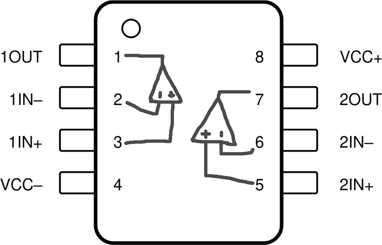
We're going to be using some op-amps today, but we're going to use a different package than before. We used the L272 op-amps when powering the motors because those op-amps were designed to be able to source a lot of current (which the motors needed in order to spin). For today, though, we don't particularly need a lot of current; rather, we need op-amps that can respond really quickly to their inputs. As such, we'll use a different op-amp: a TL082. Like the L272's, there are two op-amps in each TL082 package; but be really careful, because this chip has a different pin layout than the L272's do. The pinout for the TL082s is shown here (and clicking it will open a copy in a new tab):

Like with the other op-amps, a small dot on the surface of the chip marks pin 1. For any of these that you use, make sure to connect V_{\rm CC+} (pin 8) to the "+" terminal of the 9V battery and V_{\rm CC-} (pin 4) to the "-" terminal of the battery.
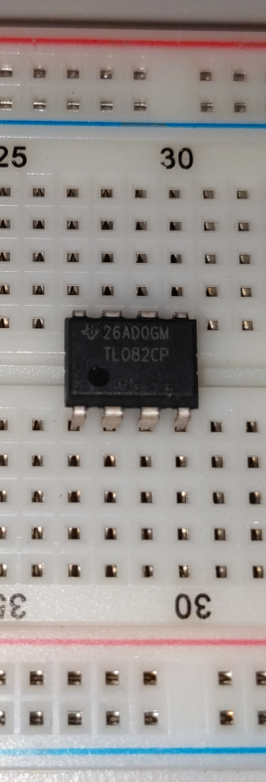
Note that the packages are labeled with "TL082" so you can tell that you've got the right component. And these packages should fit nicely right across the gap in the middle of the breadboard, like so:

If you don't do things carefully in this lab, there is a risk of messing up the sound card on whatever device you're working with. We'll try to steer you in the right direction, but just be extra careful.
We're also happy to help with things, look over schematics before you start building, etc.
Additionally, it's a good idea to disconnect the battery every time you're building anything, and only plug it back in to test.
Table of Contents
OK, for starters, we want to take our 9V battery and make a stable 4.5-Volt source (where "stable" here means that regardless of what we hook up to it, it remains at 4.5 Volts). For resistor values for this part, you probably want to use resistances around 10{\rm k}\Omega.
Once you have your schematic in hand, go ahead and build your circuit.
We suggest connecting both blue rails to the "-" side of the battery so that we have an easy way to get at that voltage.
We also suggest putting the "+" side of the battery (9V) on one of the red rails, and your new 4.5-Volt value on the other red rail, so that we have easy access to both of those as well.
Also make sure that this value doesn't change much if you connect, say, a
1{\rm k}\Omega resistor between your 4.5-Volt spot and the "-" side of the
battery.
For the rest of the lab, we're going to refer to this potential as our 0-Volt reference potential (below, we'll often refer to it as e_{\rm ref}), and, moving forward, we'll measure everything relative to that point.
So far, we've been thinking of the "-" terminal of the battery as 0V, the "+" terminal as 9V, and this new voltage as 4.5V. But moving forward, we're going to think of the "-" terminal of the battery as -4.5V, the "+" terminal as +4.5V, and the voltage we just made in the previous section as 0V.
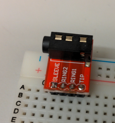
The circuit we're building here will involve processing audio, which we'll get from your computer/phone/whatever via a "TRRS" cable (tip, ring, ring, sleeve), named for the various regions of the connector, each of which carries a different signal. In order to grab those signals, we'll use a connector like this one, which will allow us to get access to those signals on our breadboard:

This connector can act either as an input or an output (and we'll actually use two of them in this lab, one for each purpose). These connectors are designed to connect to a 3.5mm audio cable:

Ultimately, we'll use one of these connectors to get an audio signal from your computer/phone/whatever onto the breadboard somewhere, create a circuit to manipulate that signal, and then use another connector to send that processed signal to a set of headphones:
I know we said in the prelab that we were going to have you solder these, but given the time constraints on the lab, we've pre-soldered a bunch (though if you finish early and want to solder your own afterwards, we have plenty of extras!). But for now just use the presoldered ones.
The various regions on the connectors carry different audio signals. Generally, these cables are meant to carry "stereo" audio signals, which have separate values for the left- and right- audio channels. TRRS connectors also generally have a connection for a microphone, but we'll ignore that here. The mapping for these signals is shown below:

For this lab, we're going to ignore the "sleeve" signal since we're not using a microphone here. Once we have audio playing through a cable plugged into this connector, we can model it like so:
The connector just wires us up (via the cable) to something in your device that is making sound (which comes to us as a voltage).
We're going to connect the pin labeled RING2 to our reference voltage so that
the voltages on the pins labeled TIP and RING1 can be thought of as being
relative to e_{\rm ref}.
Now, we would like to average these voltages together using the ideas from the prelab. Go ahead and do this, using resistances of around 100\Omega.
We're going to use this voltage v_a in a couple of different ways, and so we'll want to make sure that it's stable as well. Make a buffer to create a copy of this voltage that is stable (i.e., it won't change when we connect things up to it).
Use the second op-amp in the same package you used for your first buffer, rather than using a second TL082 package.
Now that we have an audio signal, let's go ahead and listen to it! Plug your other TRRS connector into the breadboard. On this one:
TIPandRING1to each other, and also to your buffered v_a- connect
RING2to e_{\rm ref}
We'll connect this up to headphones so that we can hear our audio. If you have headphones that have a 3.5mm audio connector (that fits into the TRRS connectors), you can feel free to use those; if not, we have some at the front of the room (which you can keep). And, if your audio source (computer or phone) doesn't have a 3.5mm headphone jack, we also have USB-C to headphone converters.
Start some audio playing. Feel free to use whatever audio you like, but something with a good bass line is probably a good bet, e.g. "Superstition" by Stevie Wonder or "I Want You Back" by the Jackson 5 or something like that, or maybe something with just a driving beat like "Toxic" by Britney Spears (which actually also has a nice bassline) or "Cruel" by St Vincent. But definitely feel free to choose something you like, too, don't just blindly go with whatever songs we suggest. Be your own person.
Once you have things connected like this and have some music playing, we'll get a voltage drop proportional to v_a - e_{\rm ref} across the headphones, which should result in audible music!
Here's where the real magic is going to start to happen. We're going to take that buffered v_a signal and connect it up to a circuit like the following:
Think back to last week. What we saw there was that, if v_a were a pure sine wave, the v_b would be a pure sine wave at that same frequency, but shifted and scaled down by some amount. As we increased the frequency, the amplitude of the output wave decreased.
Here, we're going to exploit that property of this circuit. We can think of v_a, when a song is playing, as being a sum of a bunch of sinusoids (you can take 6.300 or other classes about Fourier analysis to learn more of the theory behind that assertion!), and our little RC circuit works on each of those sinusoids independently; this has the effect of letting the low frequencies in v_a through unchanged, but heavily attenuating the higher frequencies.
Go ahead and add this part both to your schematic and to your breadboard.
How do v_a and v_b relate to each other? What are the obvious
similarities/differences?
Show your results so far to a staff member. Be prepared to discuss your
results (including audio and oscilloscope outputs), as well as a schematic
drawing of your circuit so far and a description of how it is working.
Since our goal is not just to isolate the low frequencies but also to amplify them, we're going to add another piece here, to scale up v_b by some amount. We can do this with a non-inverting amplifier offset by our e_{\rm ref}, something like the following:
We're also going to get a little bit fancy here and make it so that we can adjust the gain by turning a knob. We'll do this by using a potentiometer to create a variable resistance and use that resistance as part of our amplifier setup. Remember that a potentiometer consists of two variable resistances that change as we turn a knob:
Here, we'll use a 220\Omega resistor for R_2. For R_1, we'll use one leg of a 10{\rm k}\Omega potentiometer, for example the \alpha R_{\rm P} one. Thus, as we turn the knob on the potentiometer, then, R_1 will vary from approximately 0\Omega to approximately 10{\rm k}\Omega.
Now go ahead and add this module to your breadboard.
The pots fit nicely into one side of the breadboard without needing to bend their legs at all, leaving one row of holes on either side of the breadboard to which you can connect wires.
Given this layout, it's a good idea to put the pot off on its own somewhere and run wires from the op-amp's terminals over to the pot and back, rather than trying to make the pot fit in the same rows that the op-amp's terminals are occupying.
Finally, use 100\Omega resistors to average v_a (the output of our buffer
from way near the start of the lab) and kv_b (the output of the non-inverting
amplifier from the last section), and connect that output to TIP on the TRRS
so we can hear it (and make sure that you've also removed any previous
connections you made to that spot).
Also connect your probes to measure this average relative to e_{\rm ref}.
On one extreme end, the song should sound unchanged, but on the other end
we should hear a lot more bass!
Everything is yours to keep if you want it (including the circuit, the
headphones, the connectors, op-amps, breadboard, etc)!
Show your results to a staff member, and be prepared to discuss not only your
results but a complete schematic drawing of the circuit, as well as
describing how it accomplishes the result we see.