Digital-to-Analog Converter
Please Log In for full access to the web site.
Note that this link will take you to an external site (https://shimmer.mit.edu) to authenticate, and then you will be redirected back to this page.
We have a help queue active for lab! Go through the lab, answer the questions on this page, and ask for checkoffs on the queue! When you're all done with everything, you're done! If you get stuck on the way, let us know; we're happy to help!
Remember that labs are a learning experience, not a test, so take your time and understand things, and please ask us questions as you're working through!
Although we do want everyone to work individually and build their own circuits, it is also more than OK to ask friends/neighbors for help, too.
Table of Contents
One way that circuits demonstrate their usefulness is as transducers, converting signals from one domain (light, temperature, pressure, electrical, etc.) to another. We've seen examples of this in just about every lab so far; in lab 1, we were converting information about light and sound into electrical sigals, and in labs 2 and 3, we were using the joysticks and buttons to measure information about the world as well.
Last week, we took an additional step of including a microcontroller (in our case, a Teensy) and used it as an interface to take measurements about the real world and digitize them so that we could make use of them inside of a computer (to determine the position of the joystick as well as the buttons that were being pressed. This illustrates another amazingly-useful application of circuits: as interfaces between the real world and computation.
The Teensy microcontroller makes a comeback today, where we'll use it to demonstrate conversion in the other direction: rather than using the Teensy to measure analog voltages from the world, we'll use it to generate them.
The Teensy is a digital electronic device, meaning that it operates using only two types of voltages: On and Off, with "On" being a high voltage and a "Off" voltage. In the Teensy, the "On" voltage is around 3.3 Volts and the "Off" voltage is near 0V; and, as a digital device, the Teensy does not utilize voltages in between those values internally. However, if we're thinking about interfacing with the physical world, it is often useful to be able to work with analog voltages like the ones we've mostly seen so far in lab (which can take any value, not just "On" or "Off"). This lab will be an opportunity to explore that idea a little bit by building a 4-bit digital-to-analog converter, which will allow us to use the Teensy to generate a more diverse set of voltages.
Here's the circuit we'll be using today. Parts of it should look familiar from the last problem set and prelab. We'll start by analyzing this circuit, and then we'll build it and play with it a little bit to round out today's lab.
Enter your answer as a Python expression, using values V_1, V_2, V_3, V_4, and R, respectively, to refer to these values.
v_\text{out} =~
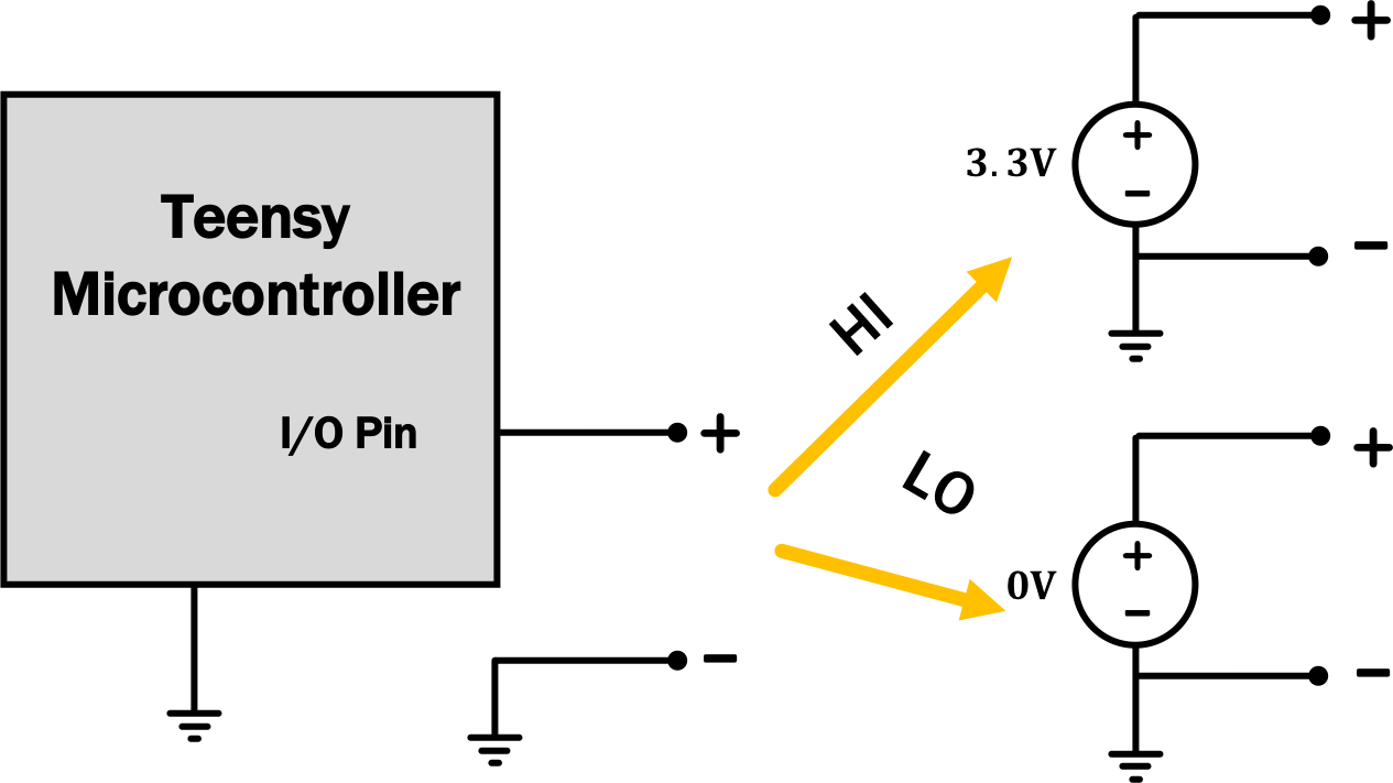
As mentioned above, this circuit is useful as a digital-to-analog converter (DAC, often pronounced like "dack" instead of "dee-eh-see"). We're going to hook it up to a Teensy microcontroller, which is only capable of producing two voltages: a "high" voltage of 3.3 Volts and a "low" voltage of 0 Volts relative to its internal ground. programmatically, we can set any pin to "high" or "low", making the corresponding pin look like this:

By hooking various pins of the Teensy up to a circuit like the one at the very top of the page, we'll be able to get a much wider variety of voltages from the Teensy.
Now that we know what to expect, we're going to build the circuit from up above, using several of the Teensy's pins to provide the voltage sources indicated there.
Since it takes a while to boot up, turn on your scope before going to grab your parts so that it can be warming up while you're grabbing things. Then grab a Teensy (make sure it says Teensy 4.0 on the bottom, not Teensy 3.2), a breadboard, and a speaker. We'll also need to cut some wires, so grab yourself some clippers as well.
For this lab, grab a full-sized breadboard since the circuit we're going to be building is pretty big (especially if you decide to try some of the optional pieces at the end).

|
|
| not the little one. | the BIG one. |
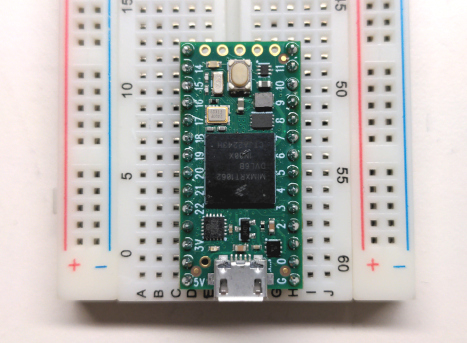
When using the Teensy with a breadboard, it's best to plug it in on the very end of the board so that it's spanning the gap in the board, with its USB jack facing outward, like so:

It can take some work to get it into the breadboard. Be careful not to break things, but it's OK to use a little bit of force to get the pins to go in.
Once you've done that, construct the circuit from the very top of the page, using pins 17, 16, 15, and 14 to provide V_1, V_2, V_3, and V_4, respectively. Use a value for R of around maybe 100\Omega or 150\Omega or so. You don't have to use those values exactly, but something in that neighborhood would be good.
Also note that the pin labeled "G" in the very corner of the board is the Teensy's internal ground. The "-" sides of the voltage sources in the circuit above are all connected to that spot internally by the Teensy (as shown below), so there are some other components we'll need to connect there as well to complete the circuit.
A partial view of a model of the Teensy's internals
We're going to use several different programs to test things today. You
can download them all here as
a ZIP file. To start, we're going to use the program called "stepper"
(stepper/stepper.ino inside of that ZIP file), which you should flash to
your Teensy using the same process as last week (but select Teensy 4.0 under
Tools\toBoard in the menu instead of 3.2).
If you use channel 1 on the scope to measure v_\text{out}, you should see something like this:

Use the cursors on the scope to measure various properties of the wave to see whether they agree with the theory from above:
- What is the maximum voltage in that waveform?
- What is the spacing (in volts) between the voltage levels?
Given the pattern you see, how is the Teensy toggling the pins? Can you predict the pattern? Try using your scope to measure the individual pins after you have a hypotheses. Does it make sense that changing them in this way causes the pattern we see in v_\text{out}?
Discuss your results so far with a staff member. How
did you solve for the values in the circuit at the top of the page? Do your
experimental results match the theory?
Now load the "sine" program (sine/sine.ino in the ZIP file) and continue
measuring the output. Try changing the frequency in the code file (the
variable called freq near the top of the file) and flashing it again. You
should see things change on the scope in a predictable way.
Now hook up a speaker at the output. you should hear a pure tone. But look at the scope!!! What changed about your signal?
Let's see if we can understand this change using circuit theory. But oh, no!
The DAC is a complicated circuit with four indendently-controllable voltage sources
and nine resistors . It wasn't too bad to analyze using series/parallel
combinations and divider relationships, but still...it sure would be nice if we
could model it as a simpler circuit instead...
Thankfully, as we saw in lecture, we do have a way to to this! We can model our whole DAC circuit (including the Teensy) with a Thévenin equivalent. Thanks, Helmholtz!
Replacing our DAC with its Thévenin equivalent, here is how we can model our circuit, with and without the speaker connected; much nicer to analyze with way fewer components!
|
|
|
| without speaker | with speaker |
Given this model, can you see why the voltage output changed when we added the speaker?
- What is the maximum voltage in the sine wave when the speaker is not connected?
- What is the maximum voltage in the sine wave when the speaker is connected?
Using those measurements, come up with an estimate R_\text{TH}. Ask a staff member for help if you're having trouble.
R.
Finally, load the "song" program (song/song.ino in the ZIP file) and flash
it to the Teensy. What happens when you run it?
This demonstrates a couple of neat things here. By introducing computation, we can work with arbitrarily-complicated signals and perform arbitrarily-complicated operations easily. And using our circuit, we can take those results and turn them into something that the scope/speaker can use!
Discuss your results with a staff member. How did you
calculate R_\text{TH} using the scope measurements? How did you calculate it
using circuit theory? Demonstrate the song playing as well.
Clean Up!
That's the official end of the lab (though if you want to keep playing, go ahead; there are some ideas below!). When you're done, clean up by:
- removing wires, resistors, and the speaker (but not the Teensy) from your breadboard
- throwing away resistors and cut wires
- giving us back your Teensy, still in the breadboard
- locking your wire stripper (by closing it down and sliding the mechanical lock lever into place) and putting it back on the cart as well
- hanging the scope probes back up on the hangers
Have a good weekend!
None of the stuff here has a checkoff or affects your grade or anything like that, but if you're having fun, there are some other things you might explore:
-
Try changing the rate at which we move through the samples in the
song.inofile. What happens if you speed it up by a factor of two? What if you slow it down by a factor of 2? -
Right now, there is a lot of distortion in the audio output from the fact that we only have 16 distinct voltage levels. Try adjusting things so that your DAC uses 6 bits (or, even better, 8 bits!). How can you extend your circuit to make this happen? If you do this, change the
DAC_RESOLUTIONvariable to be your new number of bits in all of the programs, and use pins above 17 for the new bits. Thestepperandsinedemos should now produce much smoother results, and if you change#include "song_data_4bit.h"to#include "song_data_6bit.h"or#include "song_data_8bit.h", you're hear a much cleaner audio signal as well. -
Try using the Teensy's input pins to detect button presses and use those to change the frequency of a sine wave, making yourself a little musical instrument. Or, measure the (continuous) voltage from a potentiometer hooked up as a voltage divider and using that voltage to control the frequency of a sine wave so that you can smoothly go between different frequencies.
If you do try these things (or other experiments of your own), we'd love to see what you come up with! :)