Prelab 2
Please Log In for full access to the web site.
Note that this link will take you to an external site (https://shimmer.mit.edu) to authenticate, and then you will be redirected back to this page.
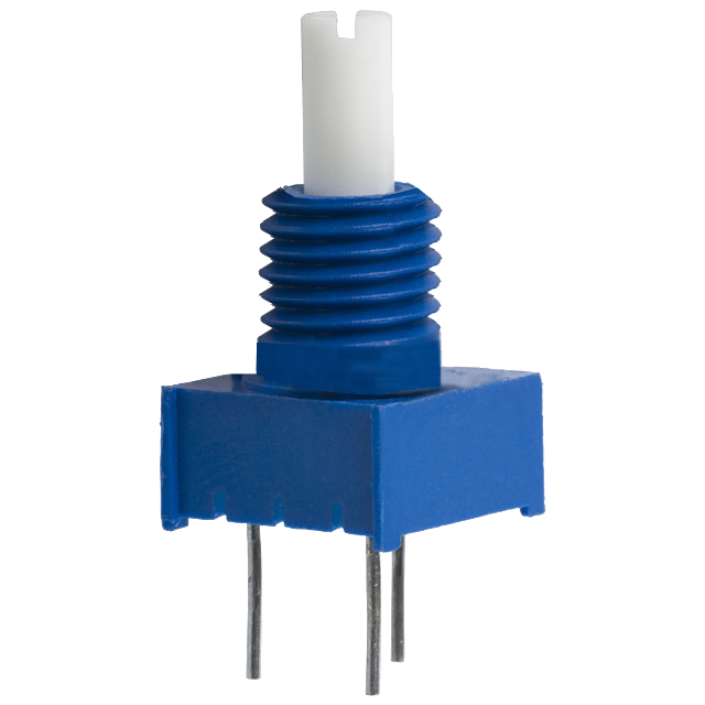
In the week 2 lab, we'll be working with a new kind of circuit component called a potentiometer (or "pot"), so this prelab is intended primarily as a first exposure to potentiometers; we'll do a little theory here so that by the time we're dealing with these components in lab, we'll be ready.
A potentiometer is a three-terminal device whose electrical properties depend on the angle of a mechanical knob. We can think of a potentiometer as being made up of two resistors, whose resistances sum to some value R_P, and whose resistances vary with the angle of the knob, which we will quantify using a number \alpha: one resistor has resistance \alpha R_P, and the other has resistance (1-\alpha)R_P. Schematically, we can represent pots in the following two ways:
The quantity \alpha corresponds to the angle of the knob, normalized to be in the range [0, 1]. \alpha=0 corresponds to the knob being turned all the way in one direction, and \alpha increases as the angle increases, until reaching \alpha=1 when the knob is turned all the way in the other direction.
As the angle of the knob increases, the resistance between the bottom and middle terminals increases and the resistance between the middle and top terminal decreases. These changes in resistance occur such that the sum of the top and bottom resistors is constant.
The illustrations below show how these resistors are actually connected inside the potentiometer:

The way this is implemented is with a single band of resistive material (total resistance R_P) and a "wiper" that moves with the knob. As the angle varies between from \alpha=0 to \alpha=1 and the wiper arm moves, the resistance between the middle terminal and each of the two outside terminals will change. The internals look something like the drawing below:
Over the course of the next few labs, we'll see some ways that we can make use of this kind of device, which will involve building a circuit like the one shown below:
For the voltage divider configuration above, what is the value of v_{out} we expect (in Volts) when \alpha=0? When \alpha=1? When \alpha=0.5?
Enter your answers below as Python expressions. Your expressions can involve
variables V_I, R_P and/or alpha, which represent the variables V_I,
R_P, and \alpha, respectively.
What is the general relationship between v_{out}, V_I, and \alpha?
Enter your answer as a Python expression. Your expression can involve
variables V_I, R_P and/or alpha, which represent the variables V_I,
R_P, and \alpha, respectively.