Prelab 3
Please Log In for full access to the web site.
Note that this link will take you to an external site (https://shimmer.mit.edu) to authenticate, and then you will be redirected back to this page.
In the week 3 lab, we'll be building a video game controller:

In last week's lab, we experimented with all of the components on the controller and hopefully got a sense for how they work. It turns out that that's about all we'll need to know in order to understand how the controller works. We'll be connecting components to a printed circuit board ("PCB") which will connect the pieces together. We'll use a Teensy microcontroller to provide power to the circuit and to communicate with a computer via USB.
This prelab is set up in three parts. Firstly, we'll give a brief overview of how the components from last week are connected up in the controller. Then we'll provide a brief introduction to soldering, and, finally, we'll provide instructions for setting up the software that we'll use to program the Teensy.
Please work through all parts of this prelab before coming to lab on Friday.
Table of Contents
The joystick on the left is the same kind we worked with in the week 2 lab, and we're connecting it up in precisely the same way we did in the lab, using each of the two potentiometers inside the joystick as a voltage divider. The voltage source shown here will be provided by the Teensy, which provides a constant 3.3 Volts. The voltages labeled v_\text{UD} and v_\text{LR} (proportional to the up/down and left/right positions of the joystick, respectively) are connected back up to input pins on the Teensy. Those pins will act like our oscilloscope, measuring the voltage there and letting us access that measurement in software.
Each push-button is also connected similarly to what we saw in lab, so that when it is pressed, the voltage on the associated pin (relative to ground) drops to zero; but when it is open, the associated pin sits at 3.3 Volts relative to ground.
The PCB has all of the wires we need connected up in the right places; our job is just to connect the right components to the right wires.
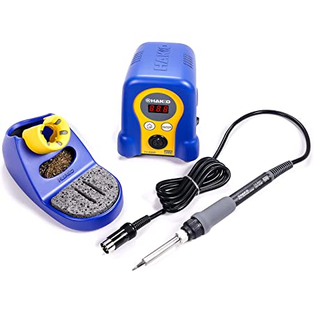
This lab is going to be our first exposure to soldering. Soldering involves joining two pieces of metal together using solder. We'll use a soldering iron like the following to accomplish this:

Note that there is a little stand (on the left) to hold the iron (bottom right), and it connects up via a cable to a little base station (in the middle) where you can turn it on and off or adjust the temperature. The grey pad is the thing you should be holding on to. The metal tip of the iron GETS REALLY HOT (it needs to in order to melt the solder), so be really careful not to touch it.
Creating a solder joint involves a few steps:
- Heat both the part (the pin sticking through) and the pad (the metal contact on the PCB) for 2-3 seconds using the iron, making sure you're in contact with both.
- Feed a small amount of solder onto the joint. It should "flow" smoothly onto the lead and make a shape like a little Hershey's Kiss.
- Continue heating for another second or so, then remove the iron.
- Let the joint cool before moving things around.
The whole process looks like the following (in real time):
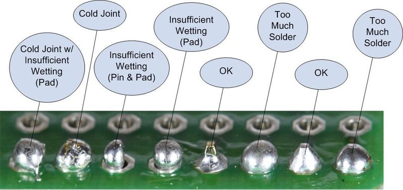
Adafruit also has a good guide to soldering, and in particular a really nice page showing several common problems and how to fix them. The following picture from that guide is a summary of some common issues:

Again, we're looking for a nice pyramid- or Hershey-kiss-shaped joint.
Soldering is not edge-of-your-seat daredevil-type stuff, but there are lots of things that can be dangerous here. Be careful, pay attention to what you're doing, and take your time; and we should all have a fun safe time.
Some things to pay attention to:
-
Wear safety goggles at all times when soldering and when clipping wires. Getting solder or flux or small pieces of wire in your eyeballs is not fun and can cause serious damage.
-
The tip of the iron gets really hot. For the love of all that is holy, don't touch it. There's a perfectly-good handle you should use instead. Minor burns can result if you touch the hot part even for a short while, and if you remain in contact with it, those burns can become serious. Seek immediate medical attention if a burn breaks the skin. The joints themselves will also stay hot for a while, so be careful when touching them.
-
Use the little vent fans we have around. The rosin in the solder vaporizes at low temperatures and can cause eye and respiratory irritation.
-
Be really careful with the iron around power cords. If the iron melts through insulation on a power cord, it can cause electric shock.
-
Wash your hands with special soap afterwards. The solder we'll use in lab has lead in it. Lead getting on your skin isn't a problem, but lead dust on your hands can result in lead getting ingested if you don't get rid of it before you eat/drink/smoke/whatever. When you're done using the solder, clean things up and then wash your hands. We have special de-leading soap at the sink in the middle of the lab room that you can use. Hand sanitizer won't work to get rid of the lead; use the special soap!
We also have a video showing the whole process of building the controller that may be worth watching as well (it's around 15 minutes long, but the soldering part only takes up maybe the first 10 minutes or so):
The circuitry involved is all stuff we went over in lab last week, but in order to alow our computer to make use of that, we're going to need to program our microcontroller to read in the relevant voltages from the joystick and buttons (corresponding to various user inputs) and communicate them to our computer.
In this section, we'll get things set up so that we can program the Teensy. At the very least, we'll get started on that process. If you aren't able to get everything working, don't worry too much; just get as far as you can, and then we can help during office hours or at the start of lab on Friday.
We'll need several pieces of software to get things working here: Arduino as an IDE, Teensyduino addon for talking with the Teensy, Arduino XInput and Teensy XInput to set up the Teensy to appear as an XBox game controller to the computer. The instructions below will talk you through the process of installing each of those.
For 6.200 this term, we'll use Arduino 1.8.19, not version 2!
It's possible that version 2 might work, but we've not tested it, so it's probably better to go with 1.8.19.
- Windows: Download and run the installer for Arduino 1.8.19.
- MacOS: Skip this step and move on to the next one.
- GNU/Linux: Download Arduino 1.8.19 for GNU/Linux and untar it somewhere using the command:
tar xvfa arduino-1.8.19-linux64.tar.gz.
- Windows: Download and run the installer for Teensyduino for Windows.
- MacOS: Download Teensyduino for MacOS and unzip it. Make sure to move it to your Applications folder (don't leave it in Downloads).
- GNU/Linux: Download the Teensyduino installer for GNU/Linux, make it executable with
chmod +x TeensyduinoInstall.linux64, and run it. If you see a warning about udev rules, run the command it suggests.
Regardless of your operating system, follow these steps:
- Download XInput v1.2.6 and make a note of where you saved it.
- Open Arduino.
- In the menu, find
Sketch\toInclude Library\toAdd .ZIP Libraryand find the file you just downloaded (xinput_1_2_6.zip). Select it and click "OK". - In the menu, choose
Sketch\toInclude Library\toXInput. Afterwards, you should see the following line appear at the top of the Arduino Editor:#include <XInput.h>.
- Regardless of your operating system, download Teensy XInput v1.1.1 and unzip it. There should be a folder inside called
teensy. - Copy the
teensyfolder from that .ZIP file into your Arduino installation, overwriting the files already in theteensyfolder there.- Windows: The relevant files are probably in
C:\Program Files (x86)\Arduino\hardware, so go there, paste theteensyfolder in, and choose "Replace the files in the destination" when asked. - MacOS: Go to Applications and then ctrl-click (or double-finger-click) on Teensyduino, then click "Show Package Contents" and go to
javaand then tohardware. Paste theteensyfolder in there and when asked, choose to overwrite the existing files.
- Windows: The relevant files are probably in
- If that worked, after restarting Arduino and choosing
Tools\toBoard\toTeensyduino\toTeensy 3.2 / 3.1, you should be able to chooseTools\toUSB Type\toXInput. If that option is available, you should be all set!