Electrocardiography Monitor
Please Log In for full access to the web site.
Note that this link will take you to an external site (https://shimmer.mit.edu) to authenticate, and then you will be redirected back to this page.
1) EKG
In today's lab we will be building a very basic EKG or ECG (electrocardiography) monitor.1 This is a fun tool to get more experience with op amps and the circuits we have discussed in class. Our goal for today's lab is to see a pulse, coresponding to your heart beat on the ocsilloscope. This should not be used as a diagnostic tool, if you have any concerns you should talk to a medical doctor. Also, everyone is different, while we will suggest values we might need to work together to tune the circuit for you and the specific placement of electrodes. That doesn't mean anything is wrong with you, we are happy to help at any point in the process, just ask!
An ECG works by measuring the electrical pulses that correspond to the contractions of different heart muscles. The ECG does not apply any electricity, it only measures the naturally occuring difference in electric potentials in the body. These electrical pulses are extremely difficult to measure for a few reasons:
- Low amplitude: Typical ECG measurements are between a few \rm{\mu}V and 5 mV. This means we need to amplify the signal significantly.
- High noise: Since the measurement has a low amplitude it is hard to tell a difference between general noise and the actual signal we are trying to sense.
- Differential measurement: We need to measure the difference in electric potential betwen two points with a common reference point.
In a real medical application, the electrodes which measure the heart impulses are placed on the chest: one on the right side and one on the left. Then a reference (essentially '0 V') is placed on the wrist or ankle. This measurement makes up Einthonven's Triangle.
For today's lab we will be doing an adjusted version of this measurement, where we will place the electrodes on our wrists with our reference being on the back of our hands (this makes it easy to move around and adjust the scope while hooked up).
2) Differential Amplifier
Let's start by building a differential amplifier with a gain of 1,000x. We have already seen one differential amplifier in the prelab assignment:

In this diagram v_1 and v_2 both represent an electrode (right or left side of the body) and the ground represents the reference electrode.
Pick values of R_1 and R_2 which result in a gain of 1,000 and limit the power dissipated by any resistor to less than 0.05 mW when measuring 2 mV between v_1 or v_2 and the reference voltage.
10, 20.
Resistance values:

Go ahead and grab your resistors, a TL082CP op amp, two batteries (and holders), two oscilloscope probes and a wavegen probe from the front.
The TL082CP pin out is shown below:
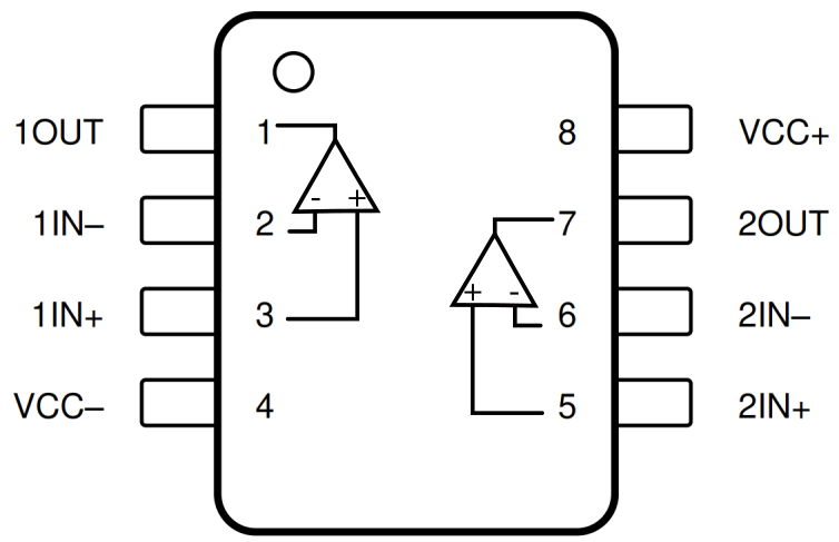
This package has two op-amps inside of it, so 1IN+, 1IN- and 1OUT correspond to one op amp. For this first example, we will only need to use one of the internal op amps. Make sure to take note of pin 1 (indicated by the dot on the package) and place your op amp across the middle of the board like we did in last week's lab.
In a real op amp, we are limited in the output voltage we can generate based on the supply voltage of the op amp (labeled VCC+ and VCC- in the TL082CP pin out). Since our ECG signal can be positive or negative with respect to our reference voltage, we are going to supply our op amp with +/- 9V, that way we can output between -9 V and +9 V (in reality this is closer to +/-8 V due to op amp limitations).
To generate these "rail" voltages, we are going to use two 9 V batteries in series, like this:

Where the mid-point will be our reference voltage (shown as the ground symbol). Think carefully about how you connect the batteries, be careful to not short the battery across its terminals.
It is also a good idea to check your battery voltage with the multimeter. If you find a bad battery, please give it to a staff member so we can dispose of it properly.
It's worth making sure that the battery is securely plugged into the battery holder, not just sitting there and sliding around inside the case. If you're having trouble plugging it in, you can use the lid of the battery holder to help, like so:
The battery holder has a small switch on the case that allows us to toggle it from "OFF" to "ON", make sure you turn it "ON" when you want to power your circuit.
For initial testing, we won't hook up the electrodes (it makes it really hard to move around and troubleshoot). Instead we are going to use our wavegen to model the type of signal we might see from the electrodes. Turn on your wavegen and set the following parameters:
- Type: pulse
- Frequency: 1 Hz
- Offset: 0 V
- Amplitude: 2 mV
- Width: 50 ms
Then connect the red and black clips from the wave gen to v_1 and v_2 in your circuit (polarity shouldn't matter).
To measure the output use an oscilloscope probe with the ground clip connected to the reference voltage.
If you haven't already, go ahead an finish building the rest of your circuit and test it out.
Be ready to talk about this during your checkoff. If you aren't sure about your output ask for help.
Once you are satisfied with the result, take a picture of your output to discuss during the checkoff.
Now lets try out the circuit as an ECG.
As mentioned earlier, there is no electricity being generated by the electrodes, only signals being sensed. There is a very small possibility of a very small shock from the 9 V battery, but only if your circuit it broken and you are effectively shorting your 9 V across your skin. This would happen in any circuit where you have a 9 V battery and accidentally short the two terminals. If your circuit worked with the wavegen supply this won't be a problem. The only other known risk in this experiment is the electrodes which have adhesive which can cause minor skin irritation. If you have very sensitive skin this you may not want to proceed. If for any reason you don't wish to do this part of the lab on yourself, you can hop on the queue to ask a staff member to test it out on themselves instead.
Go ahead and grab three electrodes and three wires with alligator clips from the front.
Remove the adhesive from the back of the electrodes one by one, placing them on you wrists. Place an electrode on the back of your wrist where you would wear a watch. Place one on the left wrist and one on the right. Then place the third electrode, which will be the reference node on the back of your hand (doesn't matter which hand).
If you haven't already, remove the wavegen probes from your circuit. Then connect the electrodes to your circuit using the alligator clips. It doesn't matter which side is v_1 or v_2 but make sure that the electrode on your hand is connected to the reference voltage (shown as the ground symbol above).
Once you place the wires, you will need to be very still to get a good measurement. Also make sure you aren't touching any other electronics (like your laptop).
Make sure to bandwidth limit your measurement. It is also helpful to AC couple your measurement on the oscilloscope since we only care about the pulse not any DC offset. To do this: click the Channel 1 button (or whatever channel you are using) and then using the appropriate option key, turn BW
Limit to be on. In the same menu, click the labeled box to AC couple.
Hmmmm....this doesn't look like what we expected. There are no pulses, and mostly just noise.
Let's try to figure out what is happening and why this set up is different compared to our wavegen input.
In our ideal circuit, our electrodes are represented a ideal voltage sources (v_1 and v_2). These voltage sources must supply current, i_x and i_y in the figure below.

Our electrodes can't supply current because we are not acting as a power source. Our electrodes can only measure difference in electric potentials, not supply power. This current also would result in voltage drops across the wires connecting to the electrodes, making the measurement even more challenging.
So we need a way to isolate the electrodes from the measurement circuit, using them only as a reference voltage without any required current. Is there a circuit we know of that acts as this kind of buffer?
Discuss your results so far with a staff member:
3) Instrumentation Amplifier
Let's try a different circuit, the instrumentation amplifier.

Just like the differential amplifier, the output voltage v_o of the instrumentaion amplifier can be written as G(v_2-v_1)
for some value of G. Find the value of G and enter it as a Python expression
in terms of the resistances in the circuit (e.g., R_1 for R_1). For now, make the
ideal op-amp assumption and ignore power supply limitations.
Hint: If you can solve for v_x and v_y, then the rest of the circuit (to the right), should look like the differential amplifier from above.
This is a more challenging design problem, we have three unknown resistor values we need to select.
Here are some general guidelines:
- Total gain should be approximately 1,000
- The gain of the differential amplifier part of the circuit should be less than or equal to 2
- R_g should be greater than 500 \Omega
Once you select your new resistors, build your new circuit. You will need to grab another TL082CP package, make sure each chip is correctly powered using the +/- 9V we generated earlier.
Start by testing your intrumentation amplifier with the wavegen, set up the same as earlier in the lab.
Once you are satisfied with the result with the instrumentation amplifier, take a picture of your output to discuss during the checkoff.
Now let's try the circuit as an ECG. Remove the wavegen and connect the electrodes in the same way as before.
Remember, be very still. It also helps to put your hands on the table, palms down.
Discuss your results with a staff member: After your checkoff, clean up by:
Default Setup Button