Metal Detector
Please Log In for full access to the web site.
Note that this link will take you to an external site (https://shimmer.mit.edu) to authenticate, and then you will be redirected back to this page.
In today's lab we will be winding our own inductor and characterizing the inductance. Then we will build an LC oscillator which will act as a metal detector!
1) Wind it up!
First, we are going to wind our own air core inductor. If you recall from 8.02, the self-inductance of a solenoid can be described with the following equation:
- L is the self-inductance
- \mu_0 is the permeability of free space 4\pi \times 10^{-7} H/m
- \mu_r is the relative permeability of the core material
- N is the number of turns
- A is the area of the core
- l is the length of the core
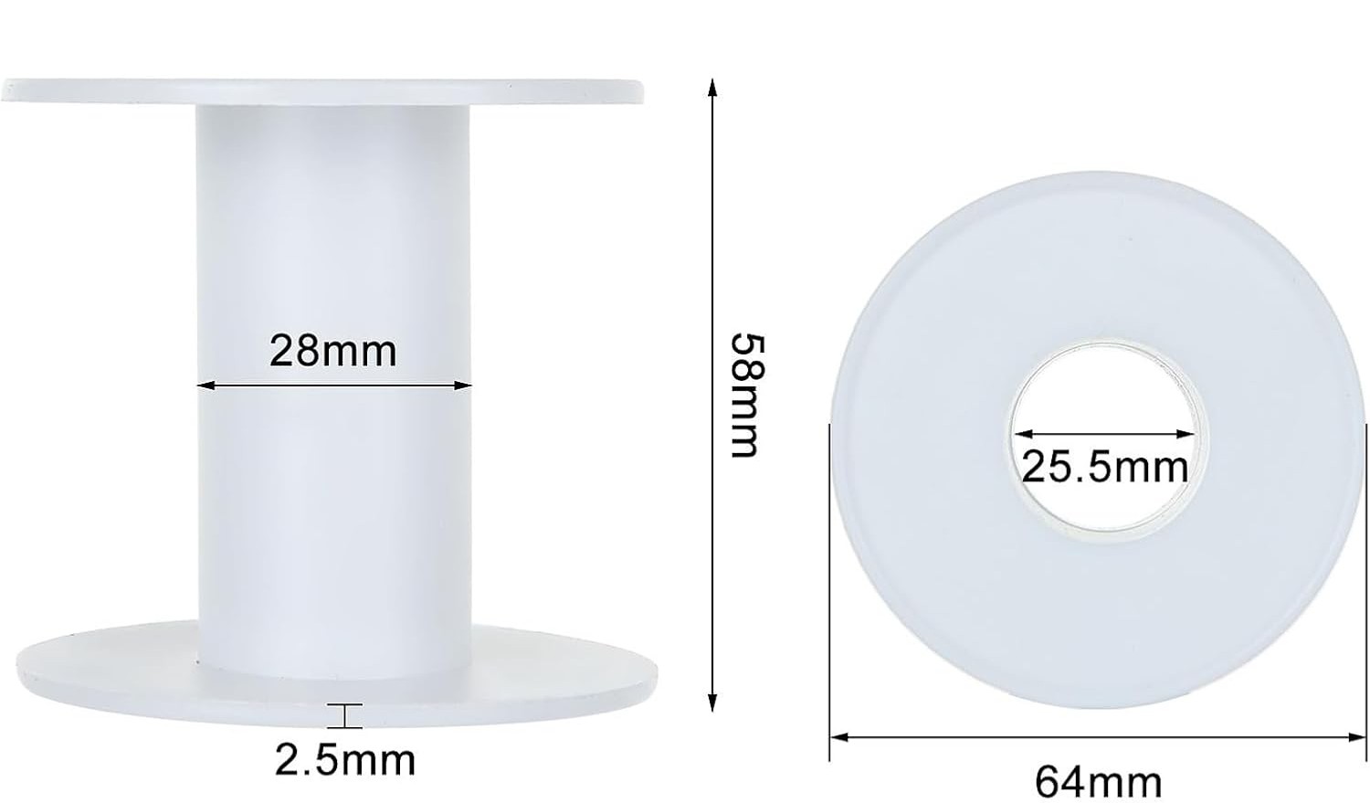
For today's inductor we are going to use a bobbin, with dimensions shown below:

Go ahead and grab some magnet wire and safety glasses from the front. Note, the magnet wire has been pre-cut to a suitable length and the ends have already been stripped so we can more easily connect to them. So do not cut the magnet wire!
There are strain relief holes on the bobbin to thread the ends of the magnet wire through to hold them in place as you wind the inductor. Make sure you have an inch or two of extra wire on the end as you start winding so that we can connect the alligator clips in the next sections.
As you wind your inductor, wear safety glasses and be aware of where the ends of your magnet wire is pointing (i.e. don't let it poke your neighbor). Be sure to keep track of the number of turns and try to make the turns as neat as possible (such that they lie flat on the bobbin in a single layer).
Show a staff member your inductor!
2) Inductor Characterization
Now, we want to characterize our inductor to see how "good" of an inductor we made. To do this, let's set up a voltage step and measure the response across the inductor.
Note, it is challenging to perform a real voltage step. If we were to try to just turn on and off our supply we would instead measure the response of our supply, not our inductor.
So instead, we are going to use a MOSFET (Metal-Oxide-Semiconductor Field-Effect Transistor). MOSFETs have many, many, many uses, but in today's lab (and next week!) we are going to use them as a switch. When configured as a switch, the MOSFET can quickly turn on and off allowing us to generate a more ideal step response.
Go ahead and grab a MOSFET and 10\Omega power resistor from the front of the room. These power resistors are a bit bigger than our typical resistors and can handle higher power dissipation.
To start, put your inductor to the side and build the circuit below:

The MOSFETs we're using should fit right into the breadboard (make sure not to short the MOSFET by placing all the pins in the same column!). Along with lots of other useful information, their datasheet will tell you which pin is which (if you have trouble finding it, let us know). In this type of MOSFET, the D stands for drain, S for Source and G for Gate.
- While the gate of the MOSFET is marked with a G, that does not mean you should connect it to ground, it should be connected to the positive of the wave gen.
In this circuit we are going to connect the positive side of the wave gen to the gate of the MOSFET and the negative side to ground, which should also be connected to the negative of your power supply (and the source of your MOSFET).
Set up your wave gen to generate a square waveform with a high voltage of 5 V and a low voltage of 0 V. Set the frequency to 1 Hz.
Use one oscilloscope probe to measure the voltage across the drain-to-source of the MOSFET and another probe to measure the wave gen.
Lastly, set up your voltage supply to 3 V output with a current limit of 1 A.
Now, let's add in our inductor, you can use alligator clips to attach your inductor to your circuit like this:

Our inductor has some inductance, some resistance and some capacitance. Today, we are going focus on characterizing the inductance and resistance. So we can model our inductor as some inductance L in series with a resistor R as shown in the circuit above.
The resistance is hopefully small enough that we cannot use a multimeter to measure it directly. Instead we need to find a way to back it out from the chacterization circuit above.
Here are some hints as you consider your chacterization method:
- Do not use a multimeter to measure the resistance.
- Measure the voltage across the inductor, not the switch (but make sure to keep all your ground clips for the scope in one location).
- Try to be as precise as possible (zoom in and measure carefully with the cursors).
- We have found higher accuracy when we trigger on the falling edge.
- Think back to the capactive touch sensor lab and how we found the capacitance.
Go ahead and perform your characterization, finding L and R.
Talk to a staff member about how you performed your characterization. How off was your inductance from the original 100 \muH goal? How large is your resistance, does the value make sense? You can go ahead and return the MOSFET, power resistor, wave gen probe and power supply connections to the front you won't need them in the last section.
2.1) Metal Detector
Now that we know our inductance, let's build a fun oscillator.
We are going to talk about how this circuit works at a high level, but please ask questions if you don't understand or if you want to dive deeper.
We can model the op amp circuitry (without the inductor and capacitor) as a resistor with a value we will call R_x. If we combine this effective resistance with the inductor and capacitor we get the following parallel RLC circuit.

To explore the response of this circuit, we are going to talk through the three different possible cases of R_x. For each case let's assume the capacitor has an initial voltage of 3.3~V.
- R_{x} = \infty~\Omega: In lecture, recitation and the nano quiz we saw the homogenous response from a pure LC circuit (i.e. R_x is infinite). Sketch the capacitor voltage under this assumption and find the frequency of oscillation.
What is the frequency of the output voltage oscillation?
- R_{x} < \infty~\Omega: We saw in the lecture demo the homogenous response when we add in a resistor with some finite positive value. Adding in this resistance means that we will be dissipating some amount of power each cycle, eventually fully discharging the capacitor voltage and inductor current. Assuming the resistance is very large (with respect to the characteristic impedance of the LC defined as \sqrt \frac{L}{C}), resulting in an underdamped system, sketch the capacitor voltage.
- R_{x} < 0~\Omega: If the resistor is negative (i.e. supplying power instead of dissipating power), we will have an interesting and very different reponse. Sketch the capacitor voltage under this condition, again assuming that the magnitude of the resistance is large such that it has little impact on the oscillation frequency.
It turns out that the op amp circuit (with positive feedback) can be modeled as a negative resistor! If you want to learn more about this, hop on the queue and we can help explain.
We are limited in output voltage by our op amp supply rails. Sketch the output voltage (using the VCVS model of the op amp), including the impact of the op amp supply voltages indicated in the oscillator circuit above. Assume that the output voltage is measured with reference to the 0~V.
Show your four sketches to a staff member. Be ready to talk through what is happening in each one.
Now let's build it! Use a 100 \Omega resistor for R_1. Pick a value of C such that your frequency is between 10-20 kHz.
Go ahead and grab a RP2040, USB cable and MCP6002 op amp from the front of the room.
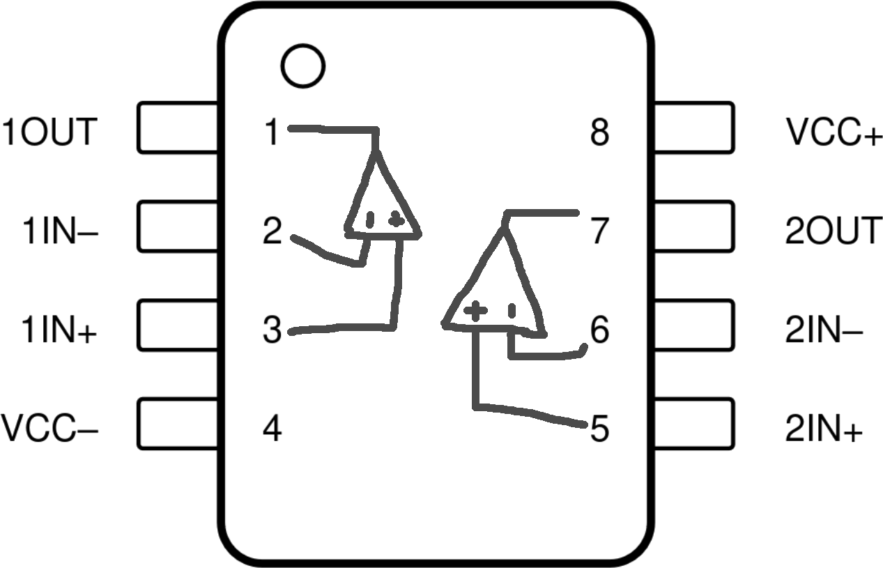
Here is a reminder of the pinout of the MCP6002 op amp:
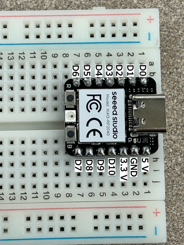
To power this op amp we are going to use the RP2040 (which recieves power through the USB cable from your laptop). You can connect your VCC+ to the 3.3 V pin and VCC- to the ground pin, referencing the pin out below:
You will need to generate the 1.65 V (which is half of 3.3 V) somehow. DO NOT USE A POWER SUPPLY
Now we are ready to test our oscillator. Probe the output voltage (referenced to your ground of the RP2040) and compare the expected operation and your sketch from Checkoff 3.
Once you are confident in your oscillator's operation, connect the output of the oscillator to pin D2 of the RP2040. Download metaldetector.zip and open up the code in Arduino.
At the top of the code find the SETPOINT_HZ variable and set it to your oscillator's frequency. Then flash the code to the RP2040.
A reminder on how to flash the code to the RP2040:
-
Under Tools->Board, make sure you have "Seeed XIAO RP2040" selected.
-
Under Tools->Port, make sure you have selected the port where the RP2040 is connected.
-
Click the little right-arrow icon to compile the code and flash it to your RP2040.
Open up the "Serial Monitor" in Arduino and see the measured frequency and error. The measured error should be low since your circuit hasn't changed yet.
Now find some metal (the handle of the wire stripper works pretty well). Watch the measured frequency as you insert the metal into the core of the bobbin. Whoa, it is changing (hopefully)! Why??
Place a speaker between pin D1 and the ground of the RP2040. What do you hear when you insert the metal into the bobbin?
Try some different types of metal, and locations of the metal. Can you hear a difference when you place the metal on top of the inductor or beside it?
Once you are done, return the RP2040 and op amp to the front of the room. You can keep your inductor!
Show your working metal detector to a staff member. Describe how we can model this oscillator and how you selected the capacitance. Be ready to talk about what happens when metal is near the inductor and how the frequency changes.