Op-Amp Dynamics
Please Log In for full access to the web site.
Note that this link will take you to an external site (https://shimmer.mit.edu) to authenticate, and then you will be redirected back to this page.
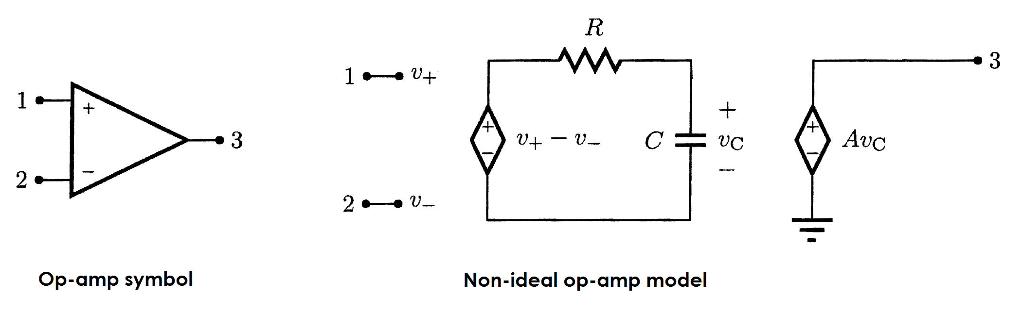
The symbol for an op-amp with its terminals enumerated is shown below to the left. The model for a non-deal version of that op-amp is shown below to the right. In addition to the traditional dependent source, this model includes a second dependent source in a series loop with the resistor R and capacitor C to model the internal dynamics of the op-amp. Note that, while not explicitly shown, v_+ and v_- are both node voltages defined with respect to ground.
The op-amp is used to build an amplifier as shown next.
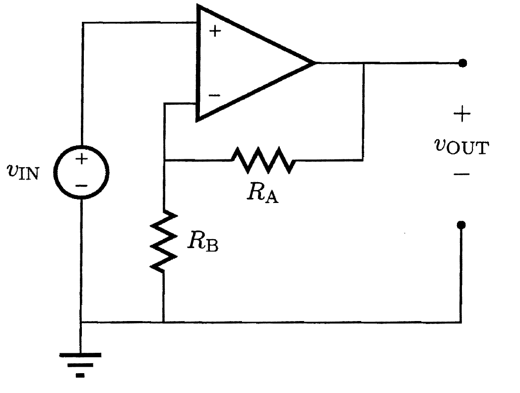
Part A
Find the differential equation that relates v_{OUT} to v_{IN}. Enter your answer in terms of the coefficients K and M, where the differential equation is expressed in the form

Part B
Now assume that the op-amp based amplifier is at rest for t < 0 with v_{IN}=0 and v_C=0. Then, at t=0, v_{IN} takes a step from 0 V to V_{IN} such that v_{IN}(t)= \begin{cases}0 & \text{if}~t<0\\V_{IN} & \text{otherwise}\end{cases}.
Using the op-amp model described above, determine v_{OUT}(t) for t\geq 0. In your answer, use exp(x) or e**x to express e^x, A for the op-amp gain A, V_IN for V_{IN}, R for R, C for C, R_A for R_A, and R_B for R_B. Note that these values are case-sensitive!
As a hint, you may find it useful to solve out in terms of K and M first, and then only sub in your values from the previous part once you have that solved.