Bridge Circuit
Please Log In for full access to the web site.
Note that this link will take you to an external site (https://shimmer.mit.edu) to authenticate, and then you will be redirected back to this page.
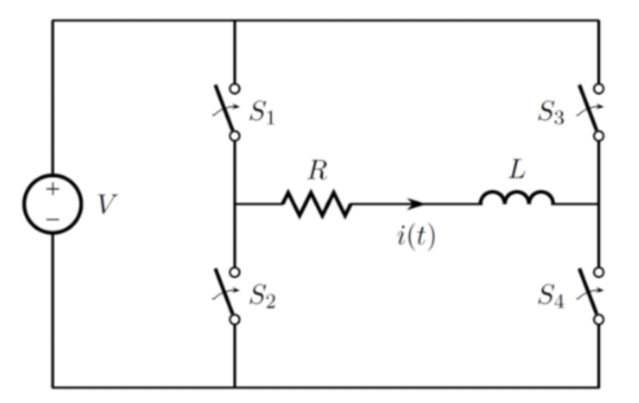
The circuit shown below can be used to regulate the current through an inductor. Typical applications include the regulation of current in motors, solenoids, and loud speakers, all of which have inductive windings. We will analyze the circuit assuming that it operates in a cyclic manner with switching period T. During the first part of each period, which lasts for a duration DT, switches S_1 and S_4 are closed while switches S_2 and S_3 are open. During the second part of each switching period, which lasts for a duration (1 − D)T, switches S_1 and S_4 are open while switches S_2 and S_3 are closed. Note that 0 ≤ D ≤ 1.
- Assume that a new switching period characterized by a given D and T begins at t = 0. In terms of the unknown i(0), determine i(t) for 0 ≤ t ≤ DT.
- Next, determine i(t) for DT ≤ t ≤ T.
- Assume further that the circuit has operated long enough to reach a cyclic steady state by t = 0 such that i(t + T) = i(t). Use your result from Part (B) to determine i(0). Note that with this result, and that from Part (A), i(t) is completely determined.
Upload your answers and work as a single PDF file, including both your answer and your
work. Please do not include any identifying information in your submission
so that we can grade the submissions anonymously.
