Relay Controller
Please Log In for full access to the web site.
Note that this link will take you to an external site (https://shimmer.mit.edu) to authenticate, and then you will be redirected back to this page.
In the circuit shown below, a transistor (modeled as an ideal switch), together with an extra resistor having resistance R_X, is used to control the current i_R through the winding of a relay. Here, the relay is modeled as a series inductor and resistor having inductance L_R and resistance R_R, respectively.
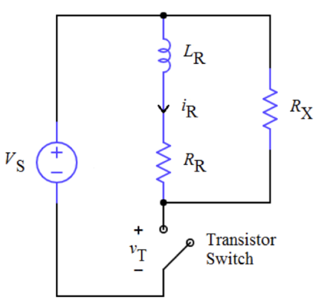
- Assume that the circuit is at rest for t < 0. Then, at t = 0, the transistor turns on (the switch closes). Determine i_R(t) for t ≥ 0 given that i_R(t < 0) = 0.
- Next, at t = T, the transistor turns off (the switch opens). Assume that T is very long so that the transient from Part (A) has reached a steady state. Determine both the relay current i_R(t) and the transistor voltage v_T(t) for t ≥ T.
- Plot your answers for parts (A) and (B): i_R(t ≥ 0), and v_T(t ≥ 0). Make sure to clearly label the graph axes and the important points on the graph.
- The relay control circuit would be less expensive without the external resistor, which may be “removed” from the circuit by considering the limit as R_X approaches infinity. Why might such a cost reduction be unwise?
Upload your answers and work as a single PDF file, including both your answer and your
work. Please do not include any identifying information in your submission
so that we can grade the submissions anonymously.
No file selected
