Motor Control 2
Please Log In for full access to the web site.
Note that this link will take you to an external site (https://shimmer.mit.edu) to authenticate, and then you will be redirected back to this page.
There are a lot of words here and a lot of experiments, but those experiments are arranged in a careful sequence. If you don't do them all (in order), it's unlikely that things will make sense. Please don't skim or skip; read carefully, work through all of the experiments and thought exercises, and ask for help when you get stuck!
Today we're going to build a little moth-like car that will follow and run away from a light as you move it. Here's a taste of what your moth-car might look like at the end of the lab:
One thing to notice about this behavior is that it requires not only responding to input light (we'll get to that later), but also making the motor turn in both directions. In the last lab, we saw that we could accomplish this by swapping the leads to the motor from the power supply. But notice here that we're not changing any of the connections to the motor; rather, we've set things up so that, depending on the strength of the light, the motor can turn in either direction.
To start, let's forget about the light-sensing part of the car and see if we can understand how to make the motor turn in both directions using a unipolar power supply.
In particular, let's start with your circuit from last week. Recover your circuit and grab a motor and a 9V battery (and connector). Hook your circuit from last week back up (you can take a look back at that lab's writeup if you need a reminder of where we were at the end of the lab).
With the circuit from last time, we were able to make four distinct voltages on one side of the motor, with the other side of the motor connected to 0V, ground, and we used that circuit to get the motor to turn in a single direction at four different speeds. Because one side of the motor was connected to ground, the current could only go one way through the motor, so it always rotated in the same direction.
Here is a drawing of our circuit from last week, where the DAC has been replaced by its Thévenin equivalent:
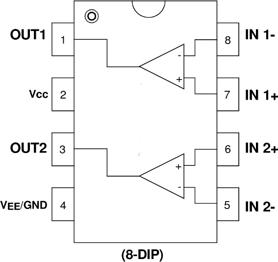
We'll also include the op-amp's "pinout" here again in case you want it as a reference (and recall that there is a little dot on the physical op-amp package marking the location of pin 1):

Hook things up and make sure you can still see the motor turning at four different speeds as you click through with the button.
Use the scope to measure the four voltages we're able to get from the (amplified) DAC, which are precisely the four distinct voltage drops we're able to produce across the motor. Write those values down.
Now we would like to now devise a circuit such that, without changing the four voltage levels emerging from the DAC, will turn the motor in either direction with two distinct speeds. You can do this by connecting one pin of the motor to the DAC output (just like we did before) and the other to a different voltage:
The goal is to make a voltage V_\text{offset} such that when the DAC is outputting its max value, the current will flow in one direction through the motor; but when it is outputting its min value, the current will flow in the other direction. We would like those two speeds to be roughly the same.
Given these design constraints, what value should V_\text{offset} be?
Now let's make that voltage. We'll start by building the following familiar circuit using a pot but not connecting it to your motor yet:
This circuit generates a branch voltage that is proportional to \alpha. Where is that voltage in the circuit above?
Hook your scope up to the wiper arm of the pot and verify that the voltage is indeed proportional to \alpha.
We would like to use this divider to make the V_\text{offset} value we drew up above (a nonzero voltage on the - side of the motor to allow the motor to spin in both directions). What value of \alpha would produce the desired V_\text{offset} you found above? Turn the knob until you are producing this voltage.
Now, with the scope still connected, hook the wiper up to the other side of the motor (as shown in the schematic above). Unfortunately, the motor does not turn for most (or maybe all) values of \alpha.
Draw a schematic diagram for the circuit and use it to explain why the motor does not turn when hooked up this way (except when \alpha is at the extreme values).
You should be able to fix this with an op-amp. Go ahead and do that (and feel free to ask for help if you get stuck!), and when you've got your motor able to turn in both directions at two different speeds, go ahead and ask for the checkoff.
Describe the results of your experiments with a staff member. In particular, be prepared to discuss:
That's all we're going to use our big board for, so before we move on, let's clean up by doing the following:
- remove all the resistors from your board and throw them away
- remove the cut wires from your board but maybe keep those for now (we might be able to reuse them for the next part)
- keep your motor, battery, and battery connector, but disconnect them from the board
- leave the Teensy in the breadboard and return it to the box near the cart labeled "Teensy Return."
- please don't try to remove the Teensy from the breadboard.
- really, seriously, just leave it in there.
- they break when people try to pull/pry them out.
- just leave it in the breadboard and turn that in.
- everything will be ok.
Now that you're all cleaned up, take a brief moment to shed a single, silent tear while reflecting on the fond memories you've made with your DAC over the past two weeks. Goodbye, old friend.
But we're going to make a new friend in the next section, so let's not spend too much time there.
Now let's build our little car. It's going to be kind of like a moth-cyclops-unicycle hybrid since it is attracted to light and it has one "eye" (a photoresistor) and one wheel. So let's call it a Cymothicycle. Anyway, regardless of how we call it, it's time to build it.
Before we can build it, though, we need a circuit design. We can take inspiration from our previous circuit, putting a control voltage of some kind on one side of the motor, and an adjustable offset voltage on the other side. In this case, rather than the voltage from our DAC, we'll use a photoresistor (like the kind we saw way back in lab 1) to make a voltage that changes with the light falling on it.
So that we can do that, let's do some experiments with the photoresistor. Grab one from the cart and use your multimeter to answer the following questions (and write down the results so that you're prepared to discuss them during your checkoff):
- What is the approximate resistance of the photoresistor in ambient light?
- What if you cover it up so that it's dark?
- What if you shine a light on it (from a phone flashlight, maybe) from 6 inches away? 3 inches away? 1 inch?
Now, knowing what we know about the photoresistor, we can go about designing a circuit to generate a voltage that varies with the light on the photoresistor. In particular, we would like to make a voltage that goes down as the amount of light falling on the photoresistor goes up.
We would like for the voltage to go down as the light gets brighter, and we would like to have as big a difference as we can between ambient light and having a bright light (like a cell phone flashlight) nearby.
We can do this with a voltage divider with our photoresistor and a separate, constant resistor, powered by the 9{\rm V} battery (similar but not identical to what we did with the photoresistor in lab 1).
Given the design goals, which of the following is the more appropriate voltage divider?
| ...or... |
So we can use something like that to provide the voltage on one side of the motor (where our DAC was in part 1). And, like we did before, we can use a potentiometer to provide an adjustable (but fixed) voltage on the other side of the motor.
Draw a complete schematic for your circuit, including the circuit for generating the control voltage, the circuit for generating the offset voltage, the motor, and any other components you might need.
Double-check:
- Will your circuit cross over the reference voltage in different lighting conditions (causing the motor to turn both directions)?
- Will either your control voltage or your offset voltage be affected by adding the motor?
If you're unsure or want us to double-check your design, feel free to ask! But either way, be prepared to discuss your schematic drawing during your checkoff.
With that design in hand, we're ready to build it! Before we build the circuit, though, let's put together the physical body of the car (we want to do this first since the physical setup will constrain/inform some of the details of how we turn our schematic into a circuit on the breadboard).
We can put together the physical body of the care as follows:
-
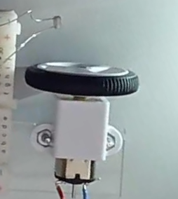
Remove the flag from your motor if you put one on it, and replace it with a wheel.
-
Grab two nuts, two bolts, a motor bracket, and a clear acrylic motor mount from the cart.
-
Put the motor bracket on the gearbox end of the motor:
-
Put one of the nuts into the little hole on top of the bracket (which is vaguely-hexagonal in shape):
-
Use your finger to hold the nut in place and turn things over with the acrylic nearby, then put the bolt through the hole and give it a few turns so it stays in place:
-
Repeat that process for the other bolt.
-
Use a screwdriver to finish tightening both bolts:
-
Stick the acrylic to the back of the breadboard (note that you can peel back the paper backing on the bottom of the breadboard to reveal some sticky-tape that you can fasten things to). Try to fasten it so that it's aligned with the breadboard as straight as possible. When all is said and done it should look something like:

Now we're ready to build our circuit!
Go ahead and lay out your design on the breadboard. It's a good idea to put the photoresistor near the wheel, pointed forward, something like:

And it's probably a good idea to leave some room near the back of the breadboard for the battery (and if it slips off, we can use some double-sided tape to fasten it down).
You are also welcome to take a toggle switch from the cart, which you can use as a way to connect/disconnect power easily (so that you don't need to plug/unplug the battery repeatedly).
Test out your little moth/cyclops/unicycle car (and maybe give it a better name than that?).
It should approach a nearby light source, then maintain a fixed distance from the light (even if the light moves), as shown in the video at the very top of the page.
When it's working, you're ready for your checkoff.
For this checkoff: Don't forget to clean up when you're done by: