Buttons, Pots, and Joysticks
Please Log In for full access to the web site.
Note that this link will take you to an external site (https://shimmer.mit.edu) to authenticate, and then you will be redirected back to this page.
We have a help queue active for lab! Go through the lab, answer the questions on this page, and ask for checkoffs on the queue! When you're all done with everything, you're done! If you get stuck on the way, let us know; we're happy to help!
Remember that labs are a learning experience, not a test, so please ask us questions as you're working through!
Although we do want everyone to work individually and build their own circuits, it is also more than OK to ask friends/neighbors for help, too.
Over the next couple weeks' labs, we're going to be building a video game controller:

Next week, we'll be learning to solder, putting together the physical controller, making all the necessary connections, hooking it up to our computer via a microcontroller. That's going to take some time, so we'll devote the whole week 3 lab to it. So that we can do that, though, we're going to take some time today to make sure we understand how the different components work. So today we'll play around with the pieces in isolation, and next week we'll put it all together.
The first component we'll look at is a button, also called a momentary switch. In a circuit schematic, we'll often draw a momentary switch like so:
While the button is pressed down, its terminals are shorted together; but when we let go of the button, its terminals are again disconnected.
Let's start by thinking about a circuit like the following, consisting of a button in series with a resistor:
What is the voltage on CH1 when the switch is open? When it is closed?
Before building, let's reset the scope to all of its defaults by:
- Pushing the "Default Setup" button in the upper left, and
- Under the "Wave Gen" menu (accessible by pushing the button in the bottom right), click the "Settings" button (the bottom one on the screen), then click the "Default Wave Gen" button (the bottom one again) You should get a message on screen saying that things have been reset.
Grab a button from the front of the room (feel free to choose any color you like) and build this circuit, using the wave generator on the scope to provide a constant ("DC") 10 Volts and connecting Channel 1 on the scope where indicated. The buttons look like this:

The button's terminals are spaced out just right so that they fit into the breadboard. Please leave them at that spacing rather than bending the terminals. (We'll be reusing these buttons later and we don't want them to get all messed up before then).
Now try pushing down the button and holding it for a while. Does the voltage on channel 1 change as you expected it to? Zoom in enough so that you can see the voltage clearly changing.
Often, we're interested in shorter button presses, though. Try pressing the button down quickly and seeing if you can see the voltage change. Use the triggering stuff we learned about last time to "capture" one of those quick button presses on the screen.
Then, without using cursors or the built-in measurement tools, just using the grid lines: how long was the button held down for? You will have to notice the time per division spec, in the top left and right parts of the oscilloscope screen respectively. The text can be very small, so be careful here. Notice that there are 10 divisions across the screen (i.e. it is the large, not the small divisions that matter).
If you are waiting for your checkoff, feel free to continue on to the next circuit, but leave this one intact so that we can talk about it with you when the time comes.
Talk about this circuit and your experiments with a staff member,
including discussing how you set the trigger to capture a button press and how
you calculated the length of the button press using the grid lines.
Next, we'll start thinking about the joysticks. But before we can get there, it's useful to think about a simpler component: a potentiometer. As we saw in the prelab, a potentiometer (or pot) is a three-terminal device whose electrical properties depend on the rotation of its mechanical shaft. We can think of a potentiometer as being made up of two resistors, whose resistances sum to some value R_p, and whose resistances vary with the rotation of the shaft, which we will quantify using a number \alpha: one resistor has resistance \alpha R_p, and the other has resistance (1-\alpha)R_p. Schematically, we can represent pots in the following two ways:
Because you have a single-turn pot (multi-turn pots exist, but aren't relevant here), the quantity \alpha corresponds directly to the angle of the potentiometer's knob, normalized to be in the range [0, 1]. \alpha=0 implies the knob is turned all the way in one direction, and \alpha increases as the angle increases, until reaching \alpha=1 when the knob is turned all the way in the other direction. As the angle of the knob increases, the resistance between the bottom and middle terminals increases and the resistance between the middle and top terminal decreases. These changes in relative resistance do not affect the sum of the top and bottom resistors, which remains constant.
The illustrations below show how these resistors are actually connected inside the potentiometer:
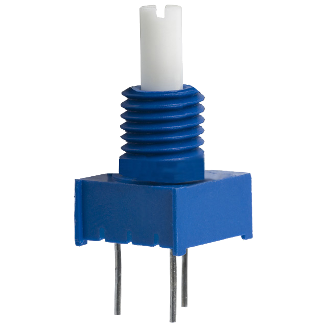
Grab a potentiometer from the front of the room. Measure its total resistance using the multimeter. Then measure the resistance between the middle terminal and one other terminal. Which resistance goes up at you turn the knob counter-clockwise? Which goes down? How big or small can they get? Be prepared to discuss these questions during your checkoff.
Next, hook up the 10V signal from the wave generator so that we are dropping 10V across the whole potentiometer (building a circuit like the one at the end of the prelab) and using channel 1 to measure the voltage drop across one side of the potentiometer. What does circuit theory say about how the voltage should change as you turn the knob on the potentiometer? Check that things are working by turning the knob and seeing the voltage on channel 1 change.
Now let's try using the variable voltage from the last section to try to light up a lightbulb. In a schematic diagram, we might draw a lightbulb like:
Grab a lightbulb from the front of the room. They look like this:
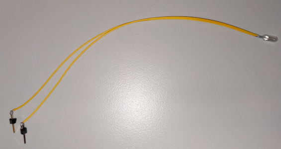
We can model this lightbulb as a resistor. Measure its resistance using the multimeter. Then, disconnect the lightbulb from the multimeter and connect it to the wave generator on the scope. Set the output to be constant 1 Volt to start, and then adjust the voltage between 0V and 10V while observing the bulb.
How does the brightness of the bulb change as the voltage drop across it changes?
Now, instead of varying the voltage on the wave gen, set it to provide a constant 10 V, and hook that up to your potentiometer as before (without the lightbulb connected).
The pot's terminals are spaced out just right so that they fit into the breadboard. Please leave them at that spacing rather than bending the terminals. The pots fit nicely into one side of the breadboard (without jumping the gap in the middle), so plug your pot in on one side of the breadboard and use wires to connect the terminals elsewhere if you want.
We have some little wires in the cabinet under the resistors, which are pre-cut to be just the right length to jump across the gaps in the breadboard. These can be a really useful way to keep things from getting too messy when building these circuits. For example, here is one way we could hook up the pot:
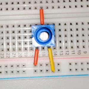
Verify that you can produce a voltage that shifts around roughly between 0V and 10V by turning the knob on the pot.
Now, add to your circuit by connecting your lightbulb between the middle terminal of the pot and ground. As you turn the knob, how does the brightness of the bulb change?
Given your previous result with directly adjusting the voltage from the wave generator, this result was probably somewhat surprising! Let's try to explain this result using circuit theory.
Use circuit theory along with modeling the light bulb as a resistor to estimate, to within 0.1 volts, the voltage across the bulb, for the values of \alpha given in the table below. Don't use a spreadsheet or a calculator. Use the resistance you measured earlier for the bulb.
Then find the value of \alpha such that the bulb voltage is 5V (one-half of its maximum value), accurate to within 10^{-3}. Hint: Draw the circuit with approximate resistor values, and look for a parallel combination.
Place these four points approximately on a graph of V_\text{bulb} versus \alpha, and sketch a smooth curve through them.
Does your plot match the results from your experiments?
Discuss the results of your experiments with the pot and the light with a staff member, including:
One of the components in the gamepad will be a joystick, which consists of two separate potentiometers in a single package (hence our earlier experiments with the pots):
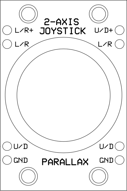
This package contains two potentiometers, which are connected to the pins labeled as follows:
Grab a joystick from the cart. Notice that the joystick has two degrees of freedom. Moving the joystick along one of its axes changes \alpha_1, and moving the joystick along the other axis changes \alpha_2. You can see this in action if you pull of the top of the joystick (you can put it back afterward, don't worry).
Plug your joystick in to your breadboard as shown in the picture below:
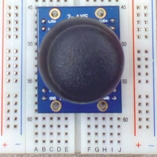
Note that there should be one row of holes on either side of the joystick package. Use these to:
- Connect
U/D+andL/R+to the positive terminal of the wave gen - Connect
GNDto the negative terminal of the wave gen - Connect channel 1 to measure between either
U/DandGNDorL/RandGND, and channel 2 to the other.
Move the joystick around and see how channel 1 and 2 change. Can you explain these changes?
Right now, the scope is displaying time on its horizontal axis, with each channel as a separate signal on the vertical axis. But that isn't particularly useful for visualizing this kind of device. So we're going to try a different kind of display: X/Y mode. Instead of separate plots of channel 1 and channel 2 versus time, this mode will cause the scope to make a single plot of channel 2 versus channel 1.
Set the scope to X/Y mode by first clicking "Acquire" (near the top middle of the panel of buttons). From the menu that pops up, set "Time Mode" (the top thing) to "XY". You should see the plot change.
Now, move the joystick around. Does the display on the scope change as you expect? Try to set things up so that the dot exactly mirrors the motion of the joystick (moving the joystick right moves the dot to the right, and so on).
It turns out that this is precisely what goes on if you've ever used a real game controller. The analog sticks are connected as voltage dividers like this, and the voltages are read into a computer to determine the player's inputs. Yet another cool example of circuits serving as an interface to the physical world (in this case, enabling a neat kind of human-computer interaction).
For extra fun, under the "Display" menu, change "Persistance" to "Variable Persistance" to cause a trace of the dot to remain for a while after it is originally drawn. Can you use this to draw a little picture or something like that?
Discuss the results of your experiments with a staff member. After your checkoff, clean up by: